


Galvanic isolation has become the mantra in the industrial engineering community as legal regulations call for its implementation in industrial system designs. Galvanic isolation allows for the exchange of information and power between two communicating points while preventing actual current flow at the same time.
Galvanic isolation has two main benefits. First, it protects people and equipment from potentially dangerous current and voltage surges. Second, it prevents the unintentional design of ground loops, whose noise would otherwise interfere with signals from data links and other interconnections.
Legacy designs of analog I/O, instrumentation, motion control, and other sensor interfaces often used single-channel isolation amplifiers to separate the sensor circuitry in the harsh environment of the factory floor from the signal-processing stage in the noise-free control room environment. Advancements in technology and design have led to new space- and power-saving digital isolators whose multichannel capability permits equipment designs with smaller form factors.
This article explains both types of isolators and their operational principles. Application examples are also provided.
Legacy isolation designs
A classic example of a legacy design using an isolation amplifier is the single-channel, isolated temperature measurement circuit in Figure 1. Here a thermocouple converts the measured temperature into a low-voltage DC output. The following resistor-diode network conditions the input signal by providing operating-point biasing, compensating for temperature drift, and boosting the input sufficiently to match the input-voltage range of the isolation amplifier.
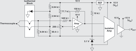
The isolation amplifier is a precision amplifier that uses duty-cycle modulation (DCM) to transmit the input signal across a capacitive isolation barrier. DCM ensures immunity to varying barrier characteristics while maintaining signal integrity. This results in high reliability and good common-mode transient immunity.
Inside the device, the input and output sections are galvanically isolated by two matched capacitors (see Figure 2). The input section converts the input voltage, VIN, into an input current, IIN, via an input resistor, RIN. Configured as an integrator, amplifier A1 integrates the difference between IIN and the current source until the input threshold of the following comparator is exceeded.
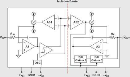
Together, the comparator and the sense amplifier, AS1, force the current source to switch at the frequency of the internal 500 kHz oscillator. The resulting drive signal into the capacitive barrier is a complementary, duty-cycle-modulated square wave.
The output section demodulates the signal from the isolation barrier through a balanced low-pass filtering. Sense amplifier AS2 detects signal transitions across the barrier and drives a switched current source into integrator A2. This stage balances the duty-cycle-modulated current against the feedback current through RF, thus yielding an average value of VOUT equal to VIN. The sample-and-hold (S/H) amplifiers in the feedback loop remove undesired voltage ripples inherent in the demodulation process.
Isolation amplifiers, while highly accurate and reliable, have several technological drawbacks. They possess a low input-signal bandwidth no greater than 50 kHz. Their requirement for a minimum power supply of ±4 V does not support modern low-voltage designs. Their expensive manufacturing process requires the separate fabrication of input and output chips, laser trimming for precise circuit matching, and final assembly of both chips together with the isolation capacitors into one package.
Modern isolation designs
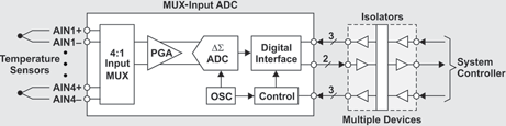
Modern data-acquisition designs use analog-to-digital converters (ADCs) whose inputs are multiplexed into a single-channel conditioning path (see Figure 3). A programmable gain amplifier (PGA) boosts the weak input signal, and the converter applies delta-sigma modulation to the signal to convert it to a digital data stream. The digital conversion results are then transmitted across the digital isolator to a system controller for further processing in the digital domain.
Digital isolators can possess various isolation barriers that use magnetic, optoelectric or capacitive isolation technologies. The isolator in Figure 4 is based on a capacitive isolation-barrier technique. The device consists of two parallel data channels, a high-speed AC channel with a bandwidth ranging from 100 Kbps up to 150 Mbps, and a low-speed DC channel covering the range from 100 Kbps down to DC.
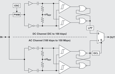
Inside the isolator, a single-ended input signal entering the AC channel is converted into a balanced signal through inverting and non-inverting input buffers. RC networks then differentiate the signal into transients, and comparators convert the transients into short pulses. A final flip-flop then converts these pulses into an output signal that is identical in phase and shape to the original input signal.
A decision logic (DCL) in the form of a watchdog timer measures the durations between signal transients. If the duration between two consecutive transients exceeds the maximum time window (as in the case of a low-frequency signal), the output multiplexer is switched from the high-speed AC to the low-speed DC channel.
Because low-speed signals lack sufficient transitions to easily cross the tiny isolation capacitors, the carrier frequency of an internal oscillator is applied to them via a pulse-width modulator (PWM). Past the barrier, a low-pass filter (LPF) removes the high-frequency content from the actual data prior to passing it on to the output multiplexer.
Industrial applications
The two most common applications for industrial data acquisition systems are in process control and factory automation. Process control systems typically detect or measure multiple physical quantities, such as tem-perature and pressure, within one system, while factory automation usually monitors one physical quantity across multiple systems.
Consequently, the configuration of data converters used in each application differs significantly. Process control systems addressing a wide range of sensor and transducer types require a wide range of parametric settings for gain, sampling rate, measurement repetition, and impedance buffering. In strong contrast, factory automation often gets along with monitoring multiple sensors of the same type, thus requiring only a minimum number of parametric settings.
Because the number of parametric settings impacts the isolation efforts and the associated costs of the digital interface design, it is important to distinguish between process control and factory automation. Two typical designs of a data-acquisition system are shown in Figures 5 and 6 to illustrate the difference.
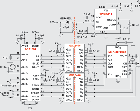
In the Figure 5 configuration, a variety of sensors measure different quantities such as temperature, pressure and current. Various gain settings maximise the input dynamic range of the ADC for each sensor. Switching between sampling rates might be necessary to match the rate of change at certain input channels. An optional power-down feature preserves ADC power when measurements are not performed. This high versatility necessitates up to eight isolated control channels.
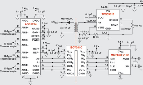
By contrast, in the Figure 6 configuration, four thermocouples of the same type measure the temperatures of different types of equipment continuously. While this design uses the same ADC as in Figure 5, the uniform sensor characteristics allow the settings for gain and sample rate to be fixed and the power-down feature to be disabled.
This system configuration drastically reduces isolation requirements because there are only four lines for data and control.
Conclusion
Isolation amplifiers are out, and digital isolators are in. To save design time and board space and to keep the cost of materials down, it is imperative to understand the system requirements before deciding what type of isolator to use.


© Technews Publishing (Pty) Ltd | All Rights Reserved
 printer friendly version