


When designing audio docking stations and accessories for portable digital audio devices, and other digital audio sources, designers are constrained by cost, while trying to deliver the highest-quality audio playback.
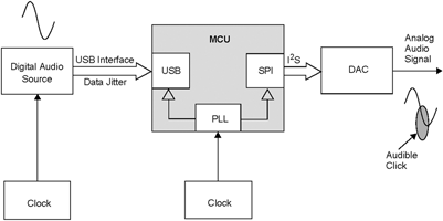
In a typical docking station and device accessory, a digital audio source that plugs into the unit sends a serial stereo audio data stream over the dock’s data transfer interface, such as USB. The dock captures the data stream while performing other crucial tasks, and routes the stream to an audio codec or digital-to-analog converter (DAC) at a specific sample rate, as shown in Figure 1.
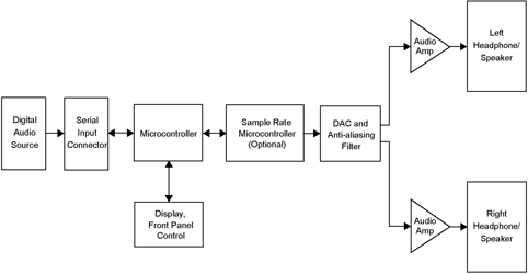
The captured stereo audio stream then flows through a serial interface to the codec or DAC. Since there are many possible sources of digitised audio, and not all of the sources use the same sampling rate, this serial interface typically adapts the sampling frequency to the source, or converts the sampled data stream into a common data rate.
Therefore, one of the challenges in the design of the docking system or device accessory is to perform the sample-rate conversion without degrading the audio quality, and at the lowest cost possible.
To deal with these challenges, designers have typically used a dedicated sample-rate conversion circuit and/or a high-end audio DAC that incorporates complex phase-locked loops (PLLs) to ensure flexible sample rates for stable communication of the sampled audio data.
The USB interface is a convenient interface for the transfer of audio data. However, to meet the requirements of professional audio, the subtle loss of quality due to USB clock and codec clock mismatch must be addressed.
In this article, the available audio-specific features of the PIC32 MCU are explored to address these needs. The SPI module supports different standard audio communication modes and offers high bit resolution for high-quality audio applications.
The flexible reference clock output feature of the PIC32 can be used to provide the master clock to the analog front-end to generate the different sample rates. The reference clock output also eliminates the need for an external crystal/oscillator by a codec.
It also eliminates the need for a PLL on the codec. The reference clock output can be tuned to prevent buffer under-run and over-run that arise because of clock mismatches. The MCU also offers the USB Host and Device module with flexible PLL clocking schemes at low power.
Digital audio data basics
When analog audio is converted into a discrete digital format, the analog signal is sampled at a frequency of at least twice the highest frequency component in the analog signal, or the Nyquist rate. Therefore, an audio signal that spans 0 to 20 kHz can be sampled at a data rate of 44,1 kHz, which in this case is the suitable Nyquist rate, so that the signal can be reconstructed without aliasing when converted back to the analog domain.
In addition to the sampling rate, data bit resolution can be 16-bit or 24-bit stereo audio data. For compact disc (CD) quality audio, the standard is 16-bit resolution with a 44,1 kHz sample rate. However, there are higher-performance CD music options. One such standard encodes the data with a 24-bit resolution and increases the sampling rate to 96 kHz.
For professional audio, the audio files are encoded with a resolution of 24 bits per sample, which provides headroom when the audio is mixed and manipulated. Also, the resolution choice allows for the trade-off of sound quality versus file size, even with compression.
The USB interface can readily handle the streaming of high-quality audio over isochronous transfers. Its ability to deliver high-quality audio is quite evident, as it is popular among many audio users. With its universal ease-of-use, USB audio can transfer high-resolution and high-sample-rate audio with negligible jitter, when packaged with a flexible audio interface.
Isochronous data transfer, amongst its various other uses, is utilised to stream audio data to and from a source at a constant rate in real-time. Stereo audio data packets, with size governed by the sample rate of the audio stream, are transferred as part of USB frames every 1 ms on the USB full-speed link. USB audio also provides controls for common features such as volume, tone, gain control and equalisers, among many control and processing units.
The differences in bit rates and sample rates require the hardware in the playback system, or dock, to be able to handle the differing rate data streams. To do that, the system must either use a more complex DAC that is expensive and can phase-lock to each sample rate and adjust itself to each playback option, or use an external sample-rate converter IC with the low-cost DAC, or convert all the streams into a standard sample rate and bit rate using an algorithm running on a microcontroller that a simple low-cost DAC can handle.
The PIC32 MCU offers a flexible reference clock output and audio mode to address these requirements to achieve high-quality audio while maintain a low design cost. The serial interface with the Audio mode and flexible reference clock output module are explored in the following sections.
PIC32 serial peripheral interface module with Audio mode
Most codecs offer serial communication over a 4-line serial interface. The transmission and reception of the stereo audio samples between the MCU and codec occur over this serial interface. Typical serial interfaces have the following signals:
* Serial Data Output (SDO) to transmit stereo audio data to the codec.
* Serial Data Input (SDI) to receive stereo audio data from the codec.
* Serial Bit Clock (SCK/BCLK) is the required bit clock provided by the Master.
* Left/Right Clock (LRCK) is the phase clock provided by the Master for stereo data.
PIC32 devices have a serial peripheral interface (SPI) module with Audio mode.
Audio mode offers various interface formats, bit resolutions and Master/Slave configurations. The communication modes supported include the following:
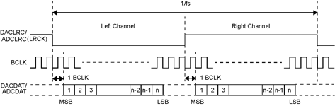
I²S format
I²S mode is where the most significant byte (MSB) is available on the second rising edge of the BCLK following an LRCK transition (Figure 2).
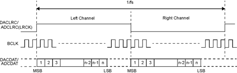
Left-justified format
Left-justified mode is where the MSB is available on the first rising edge of BCLK following an LRCK transition (Figure 3).
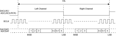
Right-justified format
Right-justified mode is where the least significant byte (LSB) is available on the rising edge of the BCLK preceding an LRCK transition and the MSB is still transmitted first (Figure 4).
DSP/PCM format
In DSP/PCM mode, the left-channel MSB is available on the first rising edge of the BCLK following a rising edge of the LRC (Figure 5). Right-channel data immediately follows left-channel data. Depending on word length, the BCLK frequency and sample rate, there may be unused BCLK cycles between the LSB of the right channel data and the next sample.
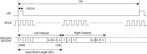
PIC32 Audio mode supports 16-, 24- and 32-bit stereo audio data. It also provides advanced error handling with receive overflow and transmit under-run flags and control bits to disable them as required. Also, the clocks generated by the BCLK and the LRC when the PIC32 MCU is a serial Master are free-running, which is essential for uninterrupted audio data transfer in streaming applications.
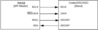
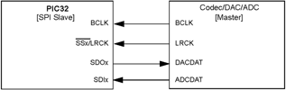
The audio codecs and DACs allow either or both of these configurations: Master or Slave. In the PIC32 SPI Audio mode Master configuration, the MCU provides the BCLK and the LRCK to the codec. This configuration is shown in Figure 6. In the PIC32 SPI Audio mode Slave configuration, the codec provides the bit clock (BCLK) and stereo phase clock (LRCK) to the MCU. This configuration is shown in Figure 7.
PIC32 devices also provide a control interface channel over the Inter-Integrated Circuit (I²C) peripheral module. The control interface is used to configure the codec for a specific mode of operation by configuring the control registers on the codecs.
Flexible reference clock output
The PIC32 devices have a flexible reference clock output. The reference clock output module (REFCLKO) can be used to generate the fractional clock that can be used by audio codec/DACs to accommodate various sample rates. Typical examples of these sample rates and associated master clocks are shown in Table 1.
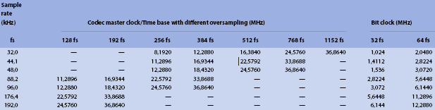
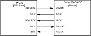
The REFCLKO module can be used to generate these audio-specific Master clocks and is not limited to just these. The reference clock can be mapped to any port pin on the device if the Peripheral Pin Select (PPS) functionality permits on the specific device. REFCLKO can be configured to the source clock for the SPI module on the PIC32 MCU instead of the peripheral bus clock.
This ensures synchronisation of the USB clock with the SPI channel clock to minimise effects of clock jitter when the USB PLL clock is selected as the source clock for the REFCLKO. The stereo word select signal and the bit clock will be synchronised with the reference clock output since all of them are sourced off the reference clock output.
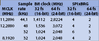
The clock source for the reference clock output module has various options. It can be selected from USB-PLL, Primary PLL, POSC, FRC, SOSC, LPRC, PBCLK, SYSCLK clocks. Based on the selected clock source, a fractional divisor needs to be configured for the REFCLKO to generate the needed MCLK based on the oversampling rate as noted in Table 2.
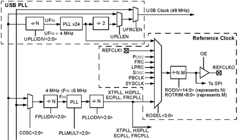
The fractional divisor needed is configured as an integer part and fractional part determined by RODIV and REFOTRIM bits in the REFOCON register, respectively. Figure 9 shows the PIC32 oscillator module with the reference clock output indicating the different clock sources for the reference clock output and the divider with the trimming scheme.
When the PIC32 SPI is the Master, the BCLK and the LRCK are generated by the device. With REFCLKO as the clock source for the SPI module, the BCLK can be configured by loading the appropriate values in the SPI baud rate generator register, SPIxBRG. If needed, the REFCLKO can provide the master clock input to the codec.
As shown in Table 2, the SPIxBRG register values and the required REFCLKO frequencies for the audio sample rates are 32/44,1/48 kHz for stereo audio data with both 16-bit and 24-bit resolution. The bit clock, BCLK, can be 32 fs or 64 fs. When the PIC32 SPI is the Slave, the BCLK and the LRCK are generated by the codec. The reference clock output can provide the master clock for the codec/DAC.
Example implementation
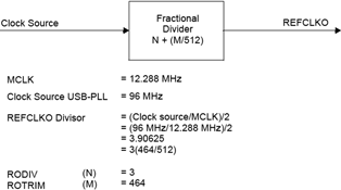
Let us explore an example of generating a REFCLKO signal. If the required MCLK is 12,288 MHz and if the USB-PLL clock of 96 MHz is used as source for the reference clock output, the required divisor is 7,8125. The divisor needs to be programmed for a half period of 3,90625, which is (7,8125/2). The RODIV bits will be configured with a value of 3 and ROTRIM configured for 464/512 = 0,90625.
Table 4 provides the required RODIV and ROTRIM values needed for the standard audio MCLKs previously listed in Table 1. The clock source selected here is the USB-PLL clock. However, any other clock source can be selected and the RODIV and ROTRIM values can be calculated in a similar manner.
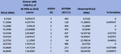
The reference clock output can be changed with a fine precision. The unit resolution is between approximately 0,02% and 0,05% based on the generated clock frequency. This ensures that the sample rate deviation is well below the limits required by the codec when the reference clock output is only being used as the SPI clock source and not as the master clock to the codec. If the reference clock output is used as the master clock for the codec, the deviation is only limited by the specification of the codec.
Table 3 shows an example of an audio master clock generated by an expensive codec with flexible internal PLL using a standard external crystal of 12 MHz and the master clock using reference clock output. The data indicate that the master clock generated by the PIC32 reference clock output is very close to the required master clock.
Also, the reference clock output performs as well as or better than the master clock generated using the internal PLL on an expensive codec. This would eliminate the need for a PLL on the codec or DAC used as an analog front end and eliminate the need for an external crystal used as time base for the codec. This will result in cost savings in the audio design while providing the same or better quality than an expensive codec.
Table 5, Table 6 and Table 7 show examples of the signal quality metrics, SNR and THD, for a set of (pure) audio tones generated using external crystal with internal PLL on the codec and using the reference clock output as master clock on the same codec.
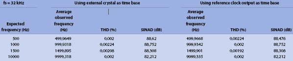
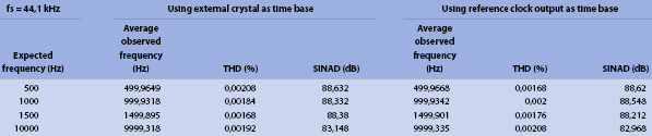
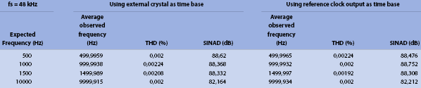
The SNR metric or signal-to-noise ratio measures the power of the noise induced compared to the signal. The higher the SNR metric the better is the quality of the signal produced.
The THD metric or the total harmonic distortion measures the strength of harmonic distortion caused by the harmonics of the fundamental frequency. The lower the THD metric the better is the quality of the signal produced.
The SNR and THD data indicates that the quality of audio signal generated by an AFE with reference clock output as the time base performs exceptionally well compared to that of a very expensive codec with internal PLL.
Tuning reference clock output
The reference clock output has the ability to be tuned on-the-fly, and can be tuned in steps between a specified range. The range should be such that it ensures a swing of the sample rate, typically about ±0,2%, which is well below a range that might introduce audible artifacts. For example, a swing of ±0,2% of the data stream with a sample rate of 48 kHz requires a tuning of the reference clock output between the ranges of 12 263 424 Hz and 12 312 576 Hz.
Table 8 lists the required RODIV and ROTRIM values for tuning the sample rate within ±200 Hz of the sample rate. The required master clock column indicates that the sample rate needs to be tuned between the range of 47,9 kHz and 48,1 kHz, ROTRIM needs to be tuned between 459 and 468 and the required RODIV is 3. Similar tuning ranges for RODIV and ROTRIM to tune the reference clock output can be determined for other standard audio sample rates.
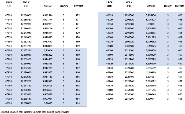
The tuning capability of REFCLKO prevents buffer under-run and over-run and alleviates the audible clicks, as discussed in the next section.
USB clock mismatch
USB specifications require a tolerance budget and a limit on the USB clock frequency as a way to achieve immunity to radio interference. The USB clock with the allowed tolerance budget results in reduced audio quality if there is a USB clock mismatch.
The real-time streaming audio samples must arrive at precise, regular time intervals so that the DAC can convert the digital samples to an analog signal with the expected constant rate at which it is configured.
The DAC clock that expects and receives the audio samples at a particular sample rate cannot miss even a single sample. A missing sample manifests as a subtle click for the listener, since the DAC fails to generate an accurate representation of the streamed audio signal.
On a microcontroller or microprocessor with an embedded USB module, the USB clock is sourced from an independent clock such as an on-chip PLL with an external crystal oscillator of specific value. Since the clock is not sourced from the USB interface, the mismatch in clocks introduces buffer over-run or under-run, causing audible clicks as shown in Figure 10.
An easy solution for the audio data under-run or over-run issue as related to audio-quality degradation, is to use a good asynchronous sample rate converter (ASRC), where the input sample rate is estimated with jitter attenuation, and the internal filters are dynamically tuned for a new sample rate. However, a good ASRC is very expensive and the system still requires a DAC for analog conversion.
As an effective low-cost solution, the USB audio packets are buffered and the clocks of the codec or DAC can be tuned to prevent under-run or over-run using a feedback mechanism. The feedback mechanism monitors the buffer level and ensures it stays within an acceptable range, while achieving at least the same quality achieved by an expensive ASRC.
The reference clock output with USB-PLL clock as its source can be used to generate and tune the required master clock, as discussed in the ‘Tuning reference clock output’ section above. This capability prevents buffer under-run and over-run while maintaining an acceptable DAC sample rate with a swing range of 0,2%. This is the lowest-cost solution compared to the other two, while still achieving high-quality audio.
Audio accessory board and application demonstration
As an example, all of the features discussed in this article are implemented in the PIC32 USB Headset application project available for the PIC32 USB Digital Audio Accessory Board.
| Email: | [email protected] |
| www: | |
| Articles: | More information and articles about Tempe Technologies |


© Technews Publishing (Pty) Ltd | All Rights Reserved
 printer friendly version