


The development DAS presented here resolves design and mathematical challenges quickly and achieves precision temperature measurement in the PRTD’s maximum range (-200°C to +850°C).
Platinum resistance temperature detectors are absolute temperature-sensing devices that can assure repeatable measurements over temperature ranges of -200°C to +850°C. Platinum, moreover, is very stable and not affected by corrosion or oxidation. PRTDs thus provide optimal performance for precision industrial and medical applications that require precise temperature measurements.
PRTDs are nearly linear devices. Depending on the temperature range and other criteria, one can make a linear approximation by calculating the PRTD resistance change over a temperature range of -20°C to +100°C.
For a wider temperature range (-200°C to +850°C) and for higher accuracy, however, the temperature-measurement PRTD standard (EN 60751:2008) defines the behaviour of platinum resistance versus temperature by a nonlinear mathematical model called the Callendar-Van Dusen equation.
Years ago, implementation of such algorithms could present both technical and cost constraints in DAS design. Today’s modern processors like the MAXQ2000 and affordable PCs can resolve these challenges quickly and cost effectively, while providing the user with a friendly graphical display.
The Callendar-Van Dusen equation can be used in such a modern DAS to reduce errors to negligible levels for the wide -200°C to +850°C dynamic range. Accuracy of ±0,3°C or better can be achieved.
Designing an example DAS
The DAS discussed in this article provides a high-resolution, low-noise measurement in the PRTD linear temperature range from -20°C to +100°C. Its accuracy is ±0,15% without implementation of the Callendar-Van Dusen equation.
By using a PRTD1000 (PTS1206-1000), a very common platinum RTD that is both size and cost effective, temperature resolution better than ±0,05°C is achievable within the given range.
This simple DAS uses a MAX11200 24-bit delta-sigma ADC for data conversion and a low-power, cost-efficient MAXQ2000 processor for data acquisition. The DAS implements the linearisation algorithm in a PC. Any other capable processor, controller or DSP could also be used.
PRTD devices like the PTS1206-1000 are an attractive choice for temperature ranges from -55°C to +155°C because they are available in standard surface-mount device (SMD) sizes, which are very similar to surface-mount resistor packages and priced in the low single-dollar range.
For temperature ranges between -50°C and +500°C, thin-film PRTDs represent a cost-effective practical choice. Thin-film PRTDs consist of thin-film platinum deposited on a ceramic substrate with a glass-coated platinum element.
Resistance and temperature deviation can be controlled to within ±0,06% and ±0,15°C, a tolerance that corresponds to Class A per EN 60751. For high-temperature measurements in liquid or corrosive environments, thin-film PRTDs are often placed inside a protective probe.
Figure 1 is a simplified schematic showing the precision DAS developed for this article. It uses the evaluation kit for the MAX11200 ADC. The MAX11200’s GPIO1 pin is set as an output to control the relay calibration switch, which selects either the fixed RCAL resistor or the PRTD.
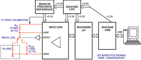
This versatility improves system precision, reduces the required calculations to those for the initial values of RA and RT, and provides excellent system diagnostics at the same time.
Equation 1 is used to calculate R(t) from the ADC’s output code:
Rt = Ra × (AADC/(FS-AADC )) (Eq 1)
Where AADC is the ADC’s output code and FS is the ADC’s full-scale code (ie, 223 - 1 for the MAX11200 in a single-ended configuration).
According to EN 60751, the PRTD range -200°C to +850°C is divided into two nonlinear temperature zones with different mathematical models. For temperatures between 0°C and +850°C, the linearisation equation requires two coefficients based on the following formula:
R(t) = R(0) × (1 + A × t + B × t²) (Eq 2)
For temperatures from -200°C to 0°C:
R(t) = R(0)[1 + A × t + B × t² + (t - 100)C × t³] (Eq 3)
Where R(t) is the PRTD resistance at t°C; R(0) is the PRTD resistance at 0°C; and t is the PRTD temperature in °C. Using Equations 2 and 3, then A, B and C are calibration coefficients derived from measurements by RTD manufacturers, as specified by IEC 60751:
A = 3,9083 × 10⁻³°C-1
B = -5,775 × 10-7°C-2
C = -4,183 × 10-12°C-4
Note that Equation 2 for temperatures between 0°C to +850°C is a quadratic and, therefore, allows a direct mathematical solution:
T+800 = [-R(0) × A + ((R(0) × A)² - 4 × R(0) × B × (R(0) - R(t))1/2]/2 × R(0) × B (Eq 4)
Where R(t) is the PRTD resistance at t°C calculated using Equation 1; R(0) is the PRTD resistance at
0°C; and t is the PRTD temperature in °C.
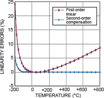
The first-order linear equation for R(t) shows large nonlinearity errors for temperatures outside the
-20°C to +100°C range. Using Equation 2 for R(t) reduces the error to negligible levels.
Table 1 shows that calculations based on Equation 4 provide measurement errors below 0,25°C which, in turn, match the nominal PRTD resistance tables for EN 60751 in the -100°C to +850°C range.
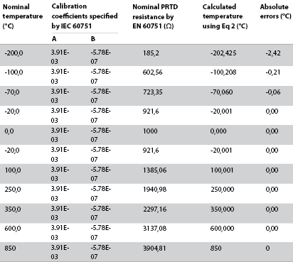
Temperature measurements with errors below 0,25°C across the -100°C to +850°C range are more than sufficient for most industrial and medical applications.
The precision provided by this development DAS is better than the Class A measurement precision prescribed by EN 60751. The ability to arrive at a direct solution (Equation 4) makes this DAS even more attractive because it substantially reduces calculation effort and complexity.
Finally, some last thoughts on Equation 3. While allowing a precision solution for temperatures between -200°C to -100°C, Equation 3 is actually a fourth-order polynomial equation that can be resolved only using computer math tools. Those tools will find the best-fit polynomial approximation expressions for the inverse transfer function or use successive approximation methods.
Processing the data
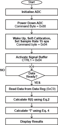
The firmware on the MAXQ2000-RAX microcontroller manages the following major functions, which are charted in Figure 3:
1. Initialises the MAX11200 ADC.
2. Collects and processes the ADC’s output data.
3. Maintains the USB interface with the PC.
During initialisation, the MAX11200 goes through the self-calibration process, sets the optimal sampling rate (10 Sps or 15 Sps), and enables the input signal buffers.
Selection of the sampling rate is very important for temperature measurement in industrial and medical applications. This DAS allows reasonably fast data acquisition with 100 dB or better power line 50 Hz/60 Hz rejection.
The recommended external clock for 60 Hz line-frequency rejection is 2,4576 MHz, which is effective for data rates of 1, 2,5, 5, 10 and 15 Sps. For 50 Hz line-frequency rejection, the recommended external clock is 2,048 MHz, which is effective for data rates of 0,83, 2,08, 4,17, 8,33 and 12,5 Sps.
Use of input signal buffers increases the input impedance to the high-megaohms range. This improves measurement precision because it practically eliminates the shunting effect of the input dynamic current.
The firmware also uses the MAX3420E USB interface and, thus, does not require driver software on the PC side. Once the DAS is connected to a PC through USB, the MAX3420E USB module is initialised and the ADC temperature conversion is ready to be transmitted.
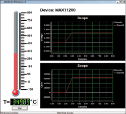
The software implements algorithms based on Equations 2 and 4. Raw measurement data is processed inside the PC. The processing sequence is shown in Figure 3; visuals of the results are shown in Figure 4.
Verification of results
To verify the accuracy of the DAS, the Fluke-724 calibrator is employed. Used as a temperature simulator, the calibrator provides precision equivalent resistance that corresponds to the output of the PRTD-1000O over the -200°C to +600°C range.
The DAS dynamically selects either the PRTD measurement or calibration measurement (1,0 kΩ, 0,1% resistor) and transmits data though a USB port to the PC. The setup is shown in Figure 5.
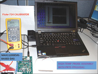
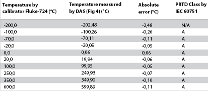
Table 2 shows that the DAS achieves better than ±0,3°C precision over the -100°C to +600°C temperature range. This performance is overall much better than Class A for EN 60751.
| Tel: | +27 11 608 0070 |
| Email: | [email protected] |
| www: | www.cstelectronics.co.za |
| Articles: | More information and articles about CST Electronics |


© Technews Publishing (Pty) Ltd | All Rights Reserved
 printer friendly version