


We need to use our limited energy resources more efficiently if we want to live sustainably. Approximately 20% of global electrical energy is consumed by lighting. At the same time we expect lighting systems to be ever more
advanced, smarter and more aesthetically pleasing.
LED lighting is becoming more popular because it is energy efficient, dimmable and its colour can be controlled with high quality. Two particularly interesting areas for LEDs are intelligent street lighting and architectural lighting. High-current, high-brightness LEDs are commonly used in both of these high-power outdoor applications.
LED lamp control with modulation
Outdoor LED lamps contain a power supply and a driver stage in the control gear, and many LEDs that are typically organised into 4, 8 or more channels. The key components of a typical power supply, as shown in Figure 1, are a bridge rectifier, a power factor correction circuit and a step-down converter, e.g. an LLC resonant converter.
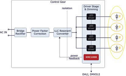
The LED currents are fixed at a carefully selected value by linear or switch-mode LED drivers. The selected LED currents depend on system components and the maximum required brightness (e.g. 350 mA or 700 mA).
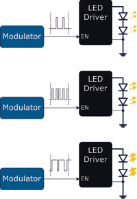
In a typical street lamp all LEDs are driven with the same current. On the other hand, multicolour lamps often used in architectural lighting may have very different LED channel currents. During dimming, which is typically triggered by communication (e.g. DALI) or sensor input (e.g. ambient light), the brightness and/or colour of the lamp are controlled by modulating the enable input of the drivers (Figure 2).
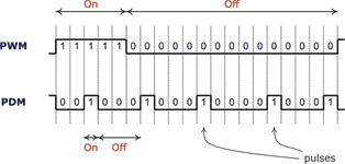
Modulation is the process of switching the LEDs on and off quickly enough that the human eye does not see it and perceives brightness depending on the average time the LEDs are on. The most common modulation methods are pulse-width modulation (PWM) and pulse-density modulation (PDM). PDM can achieve higher resolution at comparable system clocks, has more favourable EMI and is less prone to flickering due to its inherent high rate of switching.
XMC1202 and XMC1302 microcontrollers from Infineon’s XMC1000 family contain a Brightness and Colour Control Unit (BCCU) which can generate PDM signals on up to nine channels.
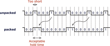
A special challenge for high-power dimmable lamps is that the LED drivers need minimum hold times, i.e. the modulated signal at the enable input of the LED driver needs to be constant for a minimum amount of time. As an example, the BCR450 linear LED driver from Infineon needs the on-time at its enable input to be a minimum of 10 μs.
As a rule of thumb, the higher the power, the longer minimum hold times needed to have stable and accurate LED current. At high resolutions and high bit rates, particularly at low brightness levels, the modulating signal may violate this requirement.
This is automatically solved in XMC1202 and XMC1302 microcontrollers by slightly rearranging the pulses in the modulating signal when required. The pulses are regrouped with a packer circuit to create new pulses that have the required minimum width without sacrificing resolution, while at the same time maintaining a flicker-free experience.
Another requirement is to minimise load changes to the power supply. LLC resonant converters in particular are sensitive to big load changes. The packer circuits in the BCCU are able to introduce a phase shift between the different channel modulation signals relative to each other, to make sure that they change state at different times.
Dimming and colour control
If modulation works as desired, it converts the brightness value into an on-off signal that controls the LEDs in such a way that they appear as bright as desired and the switching is imperceptible. Once this is achieved, the second big task is controlling the dynamic behaviour of the brightness value over time in a way that appears natural and is comfortable to the human eye.
Assuming that the LEDs are organised into multiple channels, dynamic change can be divided into two distinct transitions. One is overall brightness change, also known as dimming. The other is colour change, a change in relative intensities.
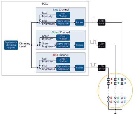
During dimming, all channels change their brightness level but their relative brightness remains the same, to preserve the colour of the lamp. The separation is achieved by generating the brightness values within the BCCU as the product of two components. These two components are the common dimming level and the channel-specific intensity.
The human eye does not sense brightness linearly. There is an approximately logarithmic relationship between physical luminance and perceived brightness. If the brightness level changes linearly over time, the eye does not perceive the rate of change as constant.
For the experience of smooth, gradual and constant change, dimming needs to be exponential. The BCCU can automatically change the dimming level along an exponential curve; the user only needs to set a new target level and the fade rate. To easily mix colours, the BCCU can also change the relative channel intensities linearly with an adjustable fade time using the automatic linear walkers.
Fast development of lighting systems
Thanks to the multi-channel architecture of the BCCU, XMC1202 and XMC1302 microcontrollers can generate the desired PDM signals for three independent LED lamps with up to nine channels, with exponentially changing dimming levels and linearly changing intensities, without complex runtime software.
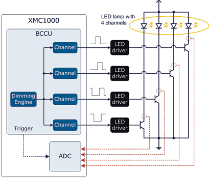
The module packs some additional extras such as dithered dimming level transitions, flicker watchdog and hardware trap for emergency shutdown. After initial configuration, the user only needs to change the target brightness, target colour and fade rate. The BCCU and ADC modules can work together for fast, time-triggered lamp signal measurements with minimum CPU load.
All these automatic features enable engineers to develop sophisticated lighting solutions fast and with a much lower risk of software bugs. Engineers can further save time with DAVE, Infineon’s software development tool-chain, by selecting and configuring dedicated lamp apps with a couple of mouse clicks, and letting the automatic code generator write the software.
High-power lamp control gear development can be kick-started by taking advantage of an available LED Lighting Application Kit.
For more information contact Davis Moodley, Infineon Technologies, +27 (0)11 706 6099, www.infineon.com


© Technews Publishing (Pty) Ltd | All Rights Reserved
 printer friendly version