


Understanding accuracy and repeatability is an important step when analysing fluid dispensing system performance. They can also be prone to misinterpretation when reviewing a product’s specification.
A dispensing motion system can be made to perform better or worse under different operating conditions. This article will explain accuracy and repeatability, and how they can be applied to different specifications. It also discusses key considerations when interpreting accuracy and repeatability for decision making.
Accuracy vs. repeatability
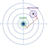
‘Accuracy’ and ’repeatability’ are commonly encountered terms used as performance characteristics of fluid dispensing equipment. Unfortunately, these terms are often confused or misunderstood. Accuracy (Figure 1) is a measure of how close an achieved position is to a desired target position. Repeatability (Figure 2) is a measure of a system’s consistency to achieve identical results across multiple tests. The ultimate goal is to have both a highly accurate and highly repeatable system.
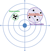
Repeatability is often expressed as the range (variation) of measurements achieved for multiple test points under consistent test conditions. Figure 2 illustrates examples of repeatable and non-repeatable processes. Thus, for the purposes of specifications, achieving smaller repeatability numbers is better because it indicates tighter groupings or a smaller range within the test data distribution.
Repeatability differs from accuracy in that it is concerned with variations in achieved results relative to each other within a given sample size.
In a fluid dispensing system, accuracy is the ability of the equipment to dispense to a target position. An accurate system is one that dispenses exactly at the target location. In order to measure accuracy, though, we really measure the individual test offset error between the achieved result and the target (ideal), as shown in Figure 1.
Thus, accuracy specifications are really expressions of the system inaccuracy and achieving a smaller specification means a system is more accurate. When specifying accuracy, however, it should not be based on a single test result, but many test results. As such, it is common practice to use the average (mean) error amongst a range of test data to express the accuracy of the entire test data distribution.
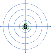
Accuracy and repeatability are closely related but are two independent specifications. It is possible for a system to be repeatable but not accurate and also possible for a system to be accurate but not repeatable. As previously mentioned, an ideal system is one that is both accurate and repeatable, as illustrated in Figure 3.
Standard deviation, Cp and Cpk
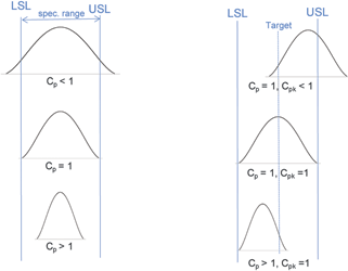
Accuracy and repeatability need to be placed in context to a specification to be meaningful. Typically, accuracy and repeatability specifications are bounded by an upper specification limit (USL) and a lower specification limit (LSL). Standard deviation, Cp and Cpk describe how accurate and repeatable a set of test results are contained within the USL and LSL.
The standard deviation, σ (sigma), is a statistical measure of the difference between individual data points to the average value of the sample of data and indicates spread of measured data. Standard deviation is calculated based on the following formula:

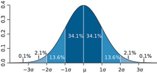
In a normal population of data points (a symmetrically balanced bell-curve, or histogram, of test samples), 99,7% of all test data will fall within ±3σ about the mean value of the data population (see Figure 4). This indicates that for a sample size of 1000, for example, three samples will then fall outside of this ±3σ range and could be considered an outlier or reject (yield loss).
Cp, known as process capability, indicates the spread of data relative to specification range. Cp is calculated based on the following formula:
A process is said to be ‘capable’ or in control when the Cp value is equal to or greater than 1,0. Using Cp, however, assumes that the centre of the data set falls at the midpoint between the USL and LSL. Therefore, it is possible to have a highly repeatable process (low variation, tight distribution of data) but be completely off target (poor accuracy) as in the case of the left group of data points in Figure 2.
Cpk, by comparison, considers both the spread of data within the specification range and location of the centre of the data relative to a target that is midway between the USL and LSL. Cpk is defined with the following formula:

Put another way, Cp is an indicator of how repeatably a system performs, while Cpk indicates how accurate and repeatable the system performs relative to USL and LSL. The process is said to meet specified capability when the Cpk value is equal to or greater than 1,0.
Conceptual differences between Cp and Cpk are shown in Figure 5. It is possible to have Cp > 1 (good repeatability) but Cpk < 1 (poor accuracy) if the distribution of data is not centred at target.
Accuracy and repeatability and specifications
Now to consider how these concepts relate to fluid dispensers and specifications for accuracy of the system. There are many factors that must be considered when generating a specification for accuracy, including the motion system, the vision system, the dispensing system and the test conditions for validating the specification.
Motion system
When considering the motion system of a fluid dispenser, there are two main factors for consideration: the resolution of detection of the system position by the system controls and the dynamic versus static condition of the motion system during a test.
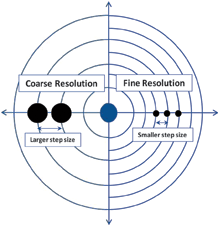
Resolution, also called step size, is the smallest possible change in movement that a motion system can detect (Figure 6). The resolution is determined by the capability of the motion system and feedback mechanism (encoder). It is typically specified by the resolution measured at the encoder.
However, this is only a measurement of the current relative positions of the encoder scale and the encoder read head. Factors such as encoder mounting location relative to the end effector, thermal expansion, frequency of encoder reading, friction and hysteresis (backlash) are used to determine an actual position of the motion system at any given instant.
The resolution of a system can indicate lower boundary of repeatability and generally better resolution can result in better accuracy. But resolution by itself does not provide accurate indication of actual performance.
Dynamic versus static condition of the motion system becomes important when examining the actual end effector (dispense valve) position at the instant of fluid dispense.
A system can be considered to be in a static condition when it has fully stopped moving and any residual oscillations from a prior move have died out. In a static condition, the encoder read position should closely correlate to the end effector position as there should be little to no relative motion between the two positions. However, it will require some settling time to achieve such a condition and thus negatively affect productivity (units per hour, UPH) of the system to achieve maximum accuracy.
If the system dispenses before any such oscillations have completely died out or the system is dynamically moving (dispensing on-the-fly), there is some induced error in the read position of the system at the encoder and the end effector’s actual position. This error will then translate to some level of degradation of the accuracy of the actual dispensing of the equipment.
End effector and fluid
The end effector and fluid type can further affect the accuracy and repeatability specifications of a given dispensing system. Valve type can affect the operation of the dispenser as a whole and thus impact the dynamic versus static conditions. The mass of the valve and the fluid reservoir will affect the inertia of the system.
Additionally, for valves or applications that require a much tighter dispense gap between the substrate surface and the dispensing tip, a system must move in the X-Y position then move down in Z position. This pause to allow motion in the Z-axis acts as an artificial settling time and can improve the actual dispense accuracy.
Similarly, the gap between the dispense tip/orifice and the substrate can create some minor offset in the fluid position if the fluid does not eject vertically down from the dispense tip to the substrate. In such a case, having a larger dispense gap introduces a larger X-Y error.
Vision system
Most automated fluid dispensers today incorporate some means of a vision system to identify target fiducials on a substrate part to locate where to dispense. As a result, the ability of a dispenser to accurately find and locate a fiducial factors into the total system accuracy.
Vision system accuracy itself has many factors affecting proper fiducial capture and finding, some of which are tied to the motion system. The frame-capture time and the correlation of a frame capture to a specific position in the dispenser’s X-Y motion area creates similar issues to those previously mentioned in the motion system section.
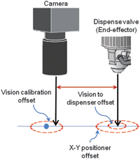
In most cases, the camera and end effector dispense point are mechanically offset from one another. In such cases, the system software must calibrate the distance between these two positions and can create an offset error if the two positions vary relative to each other or the calibration is too coarse (see Figure 7).
In addition to this, the pixel-to-micron resolution of the vision system affects the system’s inherent ability to adequately locate a fiducial feature similar to the motion system encoders. The vision system algorithm’s ability to consistently locate the target position within the captured image then affects the target positioning for where to dispense the fluid.
Substrate and fiducial imaging also depends upon having adequate lighting to create sufficient contrast in a captured image for the software to correctly identify the fiducial position. Thus, even with perfect motion system accuracy, if the vision system does not properly target the correct position, the total system accuracy can suffer.
Interpreting accuracy and repeatability specification
In evaluating performance specifications, it is important to have clear information on how claims to dispensing system specifications are obtained. Comparing data obtained under different conditions can make specification comparison difficult and can also lead to incorrect conclusions.
Artificially high positioning accuracy and repeatability could be achieved when the equipment is operated below normal speed, for example. Therefore, the evaluator must understand actual conditions for the stated specification:
* Does the specification represent a best-case scenario or a normal operating condition?
* What is the data spread of the claimed specification?
* Is the specification achieved at the positioning sensors or at the fluid dispense location?
Rather than theoretical capability at the positioning sensors, true system positioning specification is the measured capability at the fluid dispense location. True system positioning specification considers factors beyond X-Y positioning accuracy and repeatability. It also takes into consideration the effects of calibration, vision (camera) system resolution and the offset between vision system and actual dispensing position.
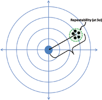
Figure 8 illustrates total system capability at the fluid dispense location in which the final system accuracy reflects both the accuracy (based on the sample set mean) and repeatability to achieve results around that mean position.
Conclusion
Accuracy and repeatability are important factors in determining fluid dispense capability. They are often the key attributes to evaluate whether equipment can meet target process parameters. However, claimed
specification numbers are highly dependent on underlining conditions.
Therefore, when comparing specifications between two systems, it is crucial to understand the complete story behind the specification. It is always recommended to check the conditions under which the claimed accuracy and repeatability are specified to determine true system specification and to be able to compare two systems equally.
For more information contact Techmet, +27 (0)11 824 1427, [email protected], www.techmet.co.za
| Tel: | +27 11 824 1427 |
| Email: | [email protected] |
| www: | www.techmet.co.za |
| Articles: | More information and articles about Techmet |


© Technews Publishing (Pty) Ltd | All Rights Reserved
 printer friendly version