


Increased thermal capacity (Tvj,op = 175°C) of 5th generation IGBTs and emitter controlled diodes from Infineon Technologies allows for an increase in output current of power modules used in inverter applications. To take full advantage of the higher junction temperature, the design of the module must evolve.
The company’s PrimePACK 3+ module incorporates .XT technology and a new design approach to enable a higher current load with no change in the form factor compared to earlier PrimePACK 3 modules.
The new PrimePACK 3+ package is implemented using a second AC bus bar and AC power terminal. This solution leads to a demonstrated reduction of the maximum internal temperature while achieving a 30% increase in current and operating at 25 K higher chip temperature with respect to the PrimePACK 3.
Extending the power range
Previously the maximum current rating available within the PrimePACK 3 housing in half-bridge configuration was 1400 A. This has been increased by approximately 30%, to 1800 A at a chip temperature (Tvj,op) of 175°C in the PrimePACK 3+ module, using .XT technology to achieve the lifetime reliability required for inverter applications.

This increase in current density was feasible only by optimising the module design with respect to its thermal management. Figure 1 shows the new PrimePACK 3+ module, which realises the full potential of the 5th generation 1200 V and 1700 V IGBT chip technology in high-power applications, with the same footprint as the well established PrimePACK 3.
The potential current density in this module is limited by the current carrying capacity of the internal bus bar. To overcome this, the design was modified with the addition of a second AC power terminal. To validate this change before production, the influence of the dual AC bus bar geometry on the current distribution and current flow in the bus bars was investigated.
Thermal analysis
To evaluate the maximum ampacity (ampere capacity) of different module designs, thermal simulations using ANSYS workbench were performed. The resulting temperature profile determines the temperatures of the points connecting the module’s bus bars to the substrates. The temperature of the module power terminals is fixed at 105°C.
The hottest area is still in the AC bus bar but the new design leads to massive improvements in this area. Even at the increased current density compared to the PrimePACK 3 and in spite of the 25 K increase in chip temperature, the maximum temperature for the bus bar is kept well within the temperature limits of the materials surrounding the hot spots. The simulation data confirms that with its dual AC bus bar geometry, the PrimePACK 3+ is well suited to leverage the full potential of IGBT5.
Current sharing between the AC terminals
To assure symmetrical and optimised current distribution, a proper external AC connection is needed. So, tests were performed to investigate current sharing and the influence of different external connection geometries for the two AC terminals. In Figure 2(b), the relative current mismatch is plotted during turn-on for four different AC connection geometries. The measurements were performed at room temperature with a DC link voltage of 900 V and a current of 1800 A.
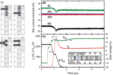
Figure 2(c) displays the waveforms for the gate voltage (VGE), collector emitter voltage (VCE) and total collector current (IC). As the waveforms of the total collector current only reveal a negligible dependence on the AC connection, Figure 2(c) includes the curves for one connection option only.
Curve (I) in Figure 2(b) represents the relative current mismatch during turn-on for connection geometry (I). Both AC terminals are connected using a massive copper stripe and a cable is attached to the outer AC terminal as schematically illustrated in Figure 2(a). For this type of connection, the highest current mismatch was observed.
Curve (II) in Figure 2(b) has been obtained from a measurement using geometry similar to (I) where the two AC terminals are connected using a massive copper stripe. However, in the case of (II), the cable was connected to terminal 10 as depicted in Figure 2(a). For (II), a larger current mismatch is observed.
For connection types (III) and (IV), the AC terminals were individually contacted with two cables of the same length and the copper bar was omitted. In case of (III), the two cables where twisted, while this was not done for (IV). In both cases, a much lower current mismatch between the two AC terminals occurs during current commutation. The lowest current mismatch is measured for the connection version (IV).
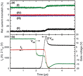
In Figure 3, the different AC connection geometries (I) to (IV) are compared for the IGBT turn-off in an analogous way as presented for the turn-on in Figure 2. The results obtained are very similar to the results from the turn-on measurements.
Version (II) exhibits the largest current mismatch, followed by types (I), (III) and (IV). The reason for the difference in the current mismatch between the on-state and the off-state can be understood considering the different di/dt of the load current in these two situations.
The minor difference between the inductances of the two AC terminals, in combination with the inductance of the connecting copper bar, leads to a slightly different di/dt in the two internal AC bus bars. When the two AC terminals are individually connected by two cables, (III) and (IV), the difference in the module’s internal inductances is small compared to the inductance of the cables, which results in closer balance of the currents.
The lowest current mismatch is obtained for an individual connection of the two AC terminals with two cables of the same resistance and inductance.
Inverter test for real application conditions
For the thermal simulations presented before, a constant terminal temperature of 105°C was assumed. In order to assess the thermal situation under real application conditions, two different modules were compared in an inverter test. This experiment was performed with a liquid cooled test inverter system.
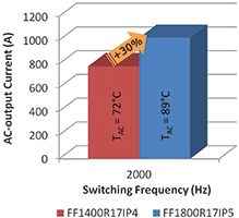
The two modules under test were the FF1400R17IP4 – a 1700 V, 1400 A IGBT4 PrimePACK 3 module – and the FF1800R17IP5 – a 1700 V, 1800 A IGBT5 PrimePACK 3+ module. The AC terminals were connected with 200 mm² copper cables forming a short loop to the connection terminal of the inverter. There was no active cooling for the terminals. Temperature sensors were attached to the AC terminal of the PrimePACK 3 and to the combined AC terminal of the PrimePACK 3+ module. In Figure 4, the results of the temperature measurements are displayed.
The temperatures of the AC terminals were measured after thermal equilibrium was established. The PrimePACK 3, FF1400R17IP4, was operated at an RMS output current of 780 A at a switching frequency of 2 kHz, which resulted in an AC terminal temperature of 72°C. For the PrimePACK 3+, FF1800R17IP5, the RMS current was increased to 1020 A at the same switching frequency, where an AC terminal temperature of 89°C was measured.
Notably, in spite of the 30% higher output current, the temperature of the AC terminals of the PrimePACK 3+ is increased by a moderate 17 K without cooling of the AC terminals.
Summary
The new PrimePACK 3+ package extends the current range of the PrimePACK series to 1800 A. The ampacity of the module is enhanced by a second AC bus bar, with large benefits for the thermal management of the module. An optimal current sharing between the two AC terminals is obtained when the two terminals are individually connected with two cables of the same resistance and the same inductance exceeding the inductance of the module’s internal AC bus bars. An inverter test demonstrates a 30% increase in current density compared to the PrimePACK 3 and leads to a moderate increase of the AC terminal temperature by 17 K.
For more information contact Davis Moodley, Infineon Technologies, +27 (0)11 706 6099, [email protected], www.infineon.com


© Technews Publishing (Pty) Ltd | All Rights Reserved
 printer friendly version