


The first part of this article ran in the 18 May 2016 issue of Dataweek.
Encapsulation discolouration
Encapsulations protect the LED chip and lead frame against certain external stresses, or act as a lens to direct the light beam. Materials ranging from epoxy, epoxy/silicone hybrid, silicone to glass are typically incorporated into LED devices. The guideline for choosing an encapsulation material for a particular application is mainly based on the material’s thermal stability, transmission performance, gas/humidity permeability and refractive index match with the LED packages.
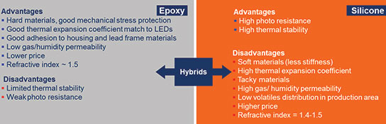
Figure 8 summarises some advantages and disadvantages of using epoxy and silicone in LEDs. Hybrid materials, which combine certain properties of epoxy and silicone, are also incorporated into LED design. Indeed, Osram Opto Semiconductors offers various LED packages with epoxy, certain hybrid or silicone encapsulation materials. The following discussion focuses on the mechanisms of specified epoxy- or silicone-based encapsulation discolouration, and provides proactive solutions for ensuring LED package performance.
Epoxy is a thermoset material with a three-dimensionally linked polymer network that is generated after curing of an epoxy resin with an anhydride hardener. During the polyaddition cure reaction step (mainly by a thermal process) each epoxide group is consumed by an anhydride hardener moiety and forms a covalent bond resulting in a rigid polyester structure without the release of detrimental by-products.
Epoxy materials possess low gas and humidity permeability and are thus good candidates for lead frame corrosion minimisation, especially for protecting silver-containing lead frame substrates against corrosive gas or sulphur compounds. They usually possess greater hardness than silicone or hybrid materials. However, epoxy has limited thermal and photo stability, and is prone to thermal oxidation and degradation.
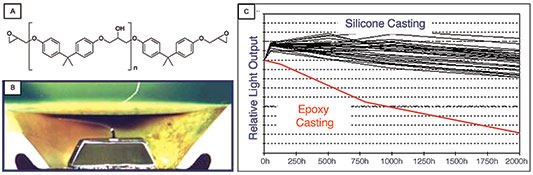
This may result in irreversible chemical bond breakages or rearrangements along the backbone functional groups. These cleaved aromatic groups are mainly responsible for the visible discolouration. The undesired discolouration affects the LED brightness and colour. Figure 9 shows the chemical structure of epoxy and demonstrates a comparison of epoxy- and silicone-based encapsulation performance in blue LED packages.
Instead of having hydrocarbon backbones, silicone derivatives (known as polymerised siloxanes or polysiloxanes) share a common chemical structure of [R2SiO]n, where an inorganic Si-O backbone is bonded with organic group R such as methyl or phenyl. The replacement of carbon by silicone molecules in the backbone leads to an overall increased bond strength, and thus silicone is more stable than epoxy against thermal and photo stresses. Variation of the Si-O chain lengths, types of side group R and crosslink ratio leads to various silicone properties, eg, different hardness, refractive index or gas/humidity permeability.
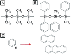
Figure 10 illustrates two silicone groups used in LED manufacturing. Depending on the requirements, one or a combination of these two silicones can be tuned to better match the refractive indexes of the die or converter materials, and to achieve a specific light output.
Although silicones have higher thermal and photo stability than epoxies and make high-power, blue or white LED assemblies possible, these silicone materials can still degrade under extensive thermal stresses and lead to LED failures. Irreversible thermal oxidation can occur, for example, due to methyl side group oxidations and further result in CH2-CH2 crosslinking between two silicone backbones.
These undesired crosslink reactions may cause an increase in silicone hardness and cracks in the material. A crack-affected LED package typically changes the overall light output or beam focus; additionally it is mostly less insulated from corrosive gases or humidity, and thus may cause lead frame corrosion-related LED failures.
Besides methyl side group oxidation, silicones may also be affected by the phenyl (aromatic)-based chromophore formation (phenyl side groups are cleaved and interact with each other to form chromophores, see Figure 10-C), which may cause optical silicone discolouration and further induce colour shift. To reduce irreversible thermal oxidation, crack formation or colour shift in a high-power LED package with silicone encapsulation, appropriate selection of silicone material and proper thermal management during the operating time should always be considered.
Volatile organic compound (VOC)-involved encapsulation discolouration is one further degradation mechanism. These volatile organic compounds may arise from outgassing of casted LED boards, polyurethane-potted electronics, polymer coated printed circuit boards (PCBs), adhesive glues, solder pastes, sealant or solder resists.
VOCs penetrate through the silicone-based encapsulations and are trapped within the casting material, when the LED device is placed in a relatively airtight environment, eg, underneath a coating layer or inside a sealed luminaire casing. During operation, high heat flux and high photonic energy generated from the chip may cause VOC oxidation or degradation, resulting typically in a thin dark layer forming on the chip surface. Although the silicone material or LED chip is generally not affected by the VOC penetration or degradation, the dark coating decreases the light output and causes colour shift.
As the chip and encapsulant material are typically not damaged by this issue, this process is usually reversible to a certain extent. Upon physical removal of the encapsulation and further running the LED for a short period (less than 100 hours), the VOC residues are either burnt out or evaporated away from the chip surface and thus the LED light output or colour hue is mostly restored.
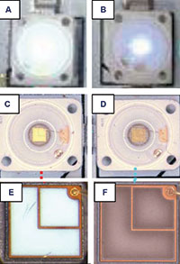
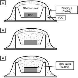
Figure 11 illustrates a schematic example of VOC-involved encapsulation discolouration. The VOCs are originated from outgassing of an incompatible coating layer applied onto the silicone lens or a casting material used on an LED board. The VOCs are ‘sealed’ underneath the casting/coating material. During the process, the VOCs gradually penetrate through the silicone lens as the silicone gas/humidity permeability typically increases at higher temperature. High radiation and heat flux generated from the LED chip result in VOC degradation, often forming a thin dark layer on the chip surface.
Figure 12 shows examples of the optical images of reference and VOC-affected LED packages without conformal coatings; the VOC penetrates through the encapsulant and the degraded VOCs at the chip surface cause light output decay and colour shift.
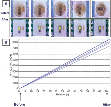
Figure 13 shows an example of improvements for VOC-affected LEDs upon the removal of outgassing sources and further operation of the LED for 72 hours. The discolouration is concentrated near the chip, where the heat and photonic energy flux are highest. For this test, the LED packages were removed from their application boards (where VOCs were released from casting material applied on the boards) and re-mounted onto the OSRAM Opto Semiconductors reliability test boards.
The silicone permeability increases with operating temperature, resulting in expedition of the VOC-based mixture leaving the encapsulation. Over a 72-hour operation period, the light output in this test recovered gradually, returning close to its specified output.
To minimise, if not avoid, VOC-involved encapsulation discolouration, careful consideration should be given before and during the application assembly. The LED package should not be placed or operated around any potentially hazardous VOCs. In addition, any conformal coating or sealants around the LED packages should not be air tight – sufficient gas exchange should be allowed for VOC escape while still maintaining insulation from corrosive gas. Customer testing is always required to ensure that no chemical compatibility issues will arise during field operation.
Testing
It is virtually impossible to compile a comprehensive compatibility list for every LED application and/or every chemical component. Therefore only certain examples are included here for some preliminary tests for reference.
The test descriptions outlined below are basic and schematic descriptions of certain main effects, goals and operation modes of these tests, but not a comprehensive description of all requirements, parameters, environments and peculiarities (including the full operation modes), which are required or recommended to execute such tests, or of all effects or results of such tests.
Likewise, the results are examples only and OSRAM Opto Semiconductors cannot assume any liability or warranty whatsoever that such results are reproducible or conclusive. Results depend on various factors, which may vary and are not completely listed in this article. All responsibility and testing obligations remain with customers.
Lead frame corrosion resistance test
The test setup is illustrated in Figure 14-A where, as a basic description, a desiccator in an oven is used as a confined environment for the material of interest. Additional humidity and temperature settings are utilised to mimic and accelerate lead frame corrosion during chemical compatibility testing.
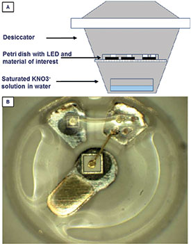
The humidity is achieved by placing saturated salt solutions (eg, potassium nitrate (KNO3) for ~92% relative humidity) in the bottom part of the chamber, with the temperature set to 40°C or 60°C. Once the humidity and temperature are well defined, the LED packages and material of interest can both be placed within the sealed desiccators during the testing period.
In general, corrosive material influence on the LED lead frame may be visible in such a test after a few days. As well as testing chemical compatibility, this method is also suitable for testing certain LED conformal coating material against corrosive chemicals, where the conformal coating should be applied first onto the LED packages.
Figure 14-B shows an LED package incubated at 40°C, 92% humidity for seven days with potentially problematic rubber foam. The regions around the silver-containing lead frame and silver-containing glue in the LED are usually affected.
There is currently no recognised international standard for testing LED lead frame resistance to H²S corrosion. The procedure for the accelerated H²S test used by OSRAM Opto Semiconductors, can roughly be described as follows:
The package of interest is placed within a sealed desiccator as illustrated in Figure 14, at 40°C, 90% relative humidity and with 15 ppm H2S for more than 1000 hours. Regarding further corrosive gas tests, the LEDs are exposed to gas mixture according to the EN 60068-2-60 Method 4 test for several package families (eg, at 25°C and 75% relative humidity, 200 ppb SO2, 200 ppb NO2, 10 ppb H2S and 10 ppb Cl2 for 21 days).
Encapsulation discolouration test
As discussed above, LED package encapsulation discolouration can result from material thermal oxidation or VOC degradation. For thermal-oxidation-related discolouration test in an LED module or array (eg, compatibility with further epoxy, silicone, polyurethane casting/potting or conformal coating), the LED package of interest can be subjected to a defined steady state life test (SSLT), with temperature and operating current held constant, monitoring for any change in the visual appearance of the LED module/array over a test period of approximately 1000 hours. In this test, an open (but not sealed) environment is required for the SSLT. However, any additional material with outgassing potential should not be placed around the LEDs under test.
For the VOC-involved discolouration test, both a sealed and a ventilated environment should be used. Test setups similar to Figure 14-A can be adopted; for a ventilated environment setup, an air pump can be installed with the desiccator to create better air circulation. The materials with potential outgassing of VOC can be placed in both sealed and ventilated chambers for comparison.
Under defined operating conditions (eg, temperature, operating current and testing periods), the effect of VOC on encapsulation discolouration should be visible. An alternative method of examining the VOC effect is to use two sealed chambers, one with the suspicious VOC material and one without the material present.
Conclusion
The purpose of this article was to provide an overview of the chemical compatibility with LED packages. It discussed certain aspects of chemical compatibility on LED performance and some mechanisms that relate to decreased light output or colour shifts, as well as basic introductions for application tests are given.
However, not all possible application environments could be covered. Awareness of material selection and precautions should always be taken into consideration with regard to the use of LEDs and, in particular, LED luminaire system assembly.
For more information contact Petrus Booyens, OSRAM Opto Semiconductors, +27 (0)79 525 1779, [email protected], www.osram-os.com


© Technews Publishing (Pty) Ltd | All Rights Reserved
 printer friendly version