


The ability to detect position or speed is a fundamental requirement in the control and monitoring of many mechanical systems. Slow speed position measurement in applications such as motorised actuators has historically used resistive potentiometers.
In high-speed applications such as servo motors, optical encoders have typically been used.
Though potentiometers are inexpensive, they suffer from the drawback of being a moving contact-based assembly, which brings the associated issues of mechanical contact wear and susceptibility to damage from external environmental factors including moisture and dirt ingress. Optical encoders offer high accuracy, but come at a higher price due to the complex nature of their construction. Engineers can solve this dilemma by using contactless rotary magnetic angle sensors that implement Hall-effect sensing.
MagAlpha sensors from Monolithic Power Systems (MPS) offer the following benefits:
• Angle resolutions from 8 to 14 bits, with SPI, ABZ, PWM and UVW interface options.
• Contactless magnetic sensing for high reliability and long application life.
• Cost-effective, space-saving packages.
• Mechanical flexibility with end or side of shaft magnet support.
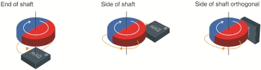
MPS MagAlpha sensors utilise a proprietary array of vertical Hall plate elements that sense the horizontal vector of the magnetic field being measured. This field typically comes from a dipole, diametrically polarised magnet situated above or to the side of the sensor. The sensing technique of the MagAlpha Hall array supports a number of magnet-to-sensor positions (see Figure 1).
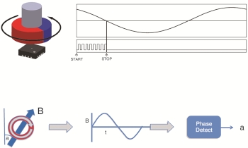
The sensor front-end contains a proprietary arrangement of Hall elements with different orientations. This array is sampled continuously at high speeds (every 1 µs) and produces an internal signal waveform, which has an approximate sinusoidal form.
The phase angle at the zero crossing point of this waveform directly relates to the angle being measured. The angle samples are digitised using a fast counter, whose value reflects the phase of the zero crossing point in each measurement period. Figure 2 illustrates the typical sampled waveform.
These accumulated samples are passed to a low-latency digital filtering block that averages out the noise and increases the resolution at the sensor output. Depending on the filter depth, resolutions up to 14 bits (3-sigma) are possible.
MPS calls this proprietary ‘phase-to-digital’ technique SpinAxis. It differs from the conventional X-Y Hall plate and arc tangent calculation technique in several ways. Traditional arc tangent based algorithms can have latencies of many hundreds of microseconds, resulting in significantly more angle lag (reported angle vs. real mechanical angle). Because of the fast sampling rate of the front-end and the low-latency design of the digital filter, the angle lag from front-end capture to the angle information being available at the output interface is typically only 10 µs.
This allows MagAlpha sensors to capture angles with low latency at very high rotation speeds. Because the latency is fixed at about 10 µs, the lag at a constant rotation speed is simply 10 µs x the rotation speed (in degrees per second). For example, at 50 000 rpm, the angle lag from acquisition to output would be 300 000 degrees per second x 10 µs = 3 degrees.
The SpinAxis technique also supports a wider range of magnetic field strengths compared to competing magnetic solutions, such as those using gross magnetoresistance (GMR) or anisotropic magnetoresistance (AMR) based materials. MagAlpha sensors can support field strengths from 15 mT to over 100 mT. This gives greater design flexibility in magnet material choice and magnet-to-sensor positioning.
Digital filter block
The digital filter block is optimised in each MagAlpha sensor type to match the target application. The filter depth (number of samples processed vs. time) affects the sensor’s final output resolution, with a greater filter depth (more samples) giving a higher resolution.
A follow-up effect of a deeper filter depth is that the filter bandwidth decreases as resolution increases (since it takes longer to process more samples). Likewise, as the bandwidth decreases, the associated time constant of the filter increases. This has an effect on the loop response time and determines how the sensor performs when used in systems where the rate of angle change or speed of rotation changes dynamically.
The filter time constant (tau) for the MagAlpha family ranges from 1 ms to 16 ms. This value can be used to compute the resulting angle lag error during acceleration or deceleration. The angle lag error under speed change is the rate of speed change in degrees per second per second (i.e. the acceleration/deceleration) multiplied by the square of the tau value.
Sensor families
Several ranges of MagAlpha devices have been created with different performances and output interface types, based on the intended application. All MagAlpha sensors output the digital angle value on an SPI bus and, in some devices, also on an SSI. In addition, specific variants offer an incremental quadrature ABZ encoder output, PWM output, or UVW commutation signals for motor control. Other features include selectable magnetic field detection thresholds to check magnet position and field strength, output linearisation registers for side shaft mode, and a programmable zero position offset.
Side-shaft linearisation allows the sensor to adjust the gain in the X or Y axis of the Hall array to compensate for the additional magnetic field vectors present in this mode, and to regain a linear output response. The zero offset adjustment means that no manual alignment of the magnet poles to the sensor’s orientation is required.
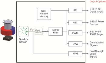
The offset can be adjusted in software for the required zero angle position. All programmable features can be stored in a non-volatile, on-chip EEPROM memory. These settings are automatically loaded after each power-on. Figure 3 shows the generic block diagram of a MagAlpha sensor.
The MA7xx family features SPI output resolutions from 9 to 14 bits, and supports SSI, ABZ and PWM interfaces. This family is suited to any general angle-sensing or speed-sensing applications including actuators, encoders and field-oriented motor control (FOC). New additions to the family include the MA732, which allows user programming of the digital filter parameters for resolution, time constant, and startup times, as well as adjustable ABZ hysteresis.
The MA780 and MA781 are designed for applications requiring low average power consumption, such as battery-powered devices. They feature low-power modes with automatic sleep, wake, and sample periods. The MA780 comes in a 3 x 3 mm QFN package, whilst the MA781 comes in a tiny 2 x 2 mm QFN package.
The MA3xx family features SPI output resolutions from 9 to 14 bits, and supports ABZ and UVW interfaces. The UVW interface can replace the motor commutation signals generated by the three individual Hall sensors found in many three-phase brushless motors. Using a simple dipole magnet, the MA3xx family is able to emulate the waveforms of three Hall sensors and generate UVW outputs supporting rotors with 1 to 8 pole pairs.
Using this combination of SPI angle or ABZ encoder output with UVW commutation allows for very compact brushless servo motor implementation. This is useful in very small diameter micro-motors where it would not be possible to embed three Hall switches in the stator windings.
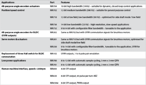
The MA330 allows greater programming of the digital filter parameters for loop bandwidth optimisation in servo motor control, and adjustable ABZ hysteresis to support higher pulse-per-turn counts for a given resolution setting.
For non-servo applications that just wish to replace the three Hall sensors, the MA102 is a minimal-feature solution that only provides the UVW signals. These are provided with complementary output polarities for greater signal-to-noise performance from the sensor wiring loom back to the motor controller.
For automotive applications, the MAQ470 and MAQ430 are AECQ Grade-1 versions of the MA702 and MA302 12-bit angle sensors, respectively. These support -40°C to +125°C operation, and are suitable for use in cabin and body sensor electronics in vehicle applications. Typical applications include infotainment controls, HVAC flap angle control, and pop-out door handles.
Lastly, for simple rotary user interface applications, the MA8xx family of 8-bit parts provides a cost-effective way to replace mechanical rotary switches or potentiometers. These also have the magnetic field threshold detection feature available in all MagAlpha parts, which allows for the implementation of a push-button action into the rotary knob design.
All MagAlpha sensors come in a space-saving 3 x 3 mm QFN package (with the exception of the MA781 in 2 x 2 mm QFN), and operate from a 3,3 V supply. Current consumption is typically in the 10 mA to 13 mA range, with micro-amp average currents possible in the new MA780 and MA781 low-power parts.
| Tel: | +27 11 608 0144 |
| Email: | [email protected] |
| www: | www.nuvisionelec.com |
| Articles: | More information and articles about NuVision Electronics |


© Technews Publishing (Pty) Ltd | All Rights Reserved
 printer friendly version