


Grintek Antennas has long been one of the leading suppliers of antennas to the local telecommunications industry and has over the years won lucrative export orders in the face of stiff international competition.
The company designs and manufactures a variety of GSM base station antennas, omni-directional and panel antennas as well as tap-off couplers for indoor GSM distribution, GSM RF amplifiers, cell extenders and dual band diplexers, a broad range of wireless LAN antennas, including patch, omni, Yagi, sector and variable gain sector antennas, and base station and subscriber antennas for DECT systems (amongst others).
Through the years we have received many questions regarding the use of different types of antennas for various applications. With this communication we present some of the most frequently used antenna types and briefly discuss some engineering applications using a beamwidth/gain table.
Antenna types
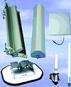
Omni-directional antennas have a 360° horizontal plane pattern and a vertical plane pattern with a beamwidth varying from typically 80° (gain 2 dBi) to 8° (gain 10 dBi). Omni antennas give continuous azimuth plane coverage, but expose the receiver system to possible undesired radiation or interference. The horizontal plane omni pattern is affected by obstructions such as masts, buildings, trees, etc.
Flat panel antennas have typical gain values ranging from 8 to 20 dBi. These antennas are usually made up of either a single radiating antenna or an array of radiating antennas. The beamwidths in the vertical and horizontal planes are usually nominally the same and typically vary from 75°x75° to around 15°x15°, depending on the area of the antenna array.
Yagi antennas can be designed to have gain values from 6 dBi (short) to 12 dBi (long) or more. The lower gain types are usually etched and compete with the low gain flat panel antennas as subscriber terminal antennas.
Sector antennas differ from patch and Yagi antennas in that they are designed to have specific horizontal plane beamwidths and usually have much smaller vertical beamwidths. This means that more energy is confined to the desired sector and less is wasted in the vertical plane. Sector antennas are ideal for applications where high gain and minimal interference are required. Variable sector antennas are ideal for in situ site optimisation or situations where the area to be covered is not known in advance. The Grintek models can be set for 90°, 120° or 180° horizontal plane coverage. Sector antennas are usually more expensive than flat panel antennas of similar gains.
Grid antennas (parabolic reflectors) have gain values typically ranging from 21 dBi to over 40 dBi. These antennas have 'pencil' beams (very narrow in both planes) and are used to cover long distances in point-to-point communication systems. These antennas are significantly bigger than the lower gain sector and panel antennas (every 3 dBi increase in gain corresponds to a doubling of the area of the panel/grid antenna or a doubling of the length of the sector/omni antenna).
Quick antenna gain calculations
Grintek has often been asked how far a specific antenna will allow the user's system to 'work'. If one knows how much power is transmitted at the one end of the link and what the receiver sensitivity (in dBm) is at the other end, the link budget can be estimated from the equation (neglecting multipath and other extraneous reflections):
This equation can be reshuffled to calculate, for instance, the required receive antenna gain, when the distance is known.
The above equation can conveniently be written in decibel form as:
PR (dBm) = PT (dBm) + GT (dBi) + GR (dBi) -20 log r (km) -20 log ƒ (MHz) - 32,44
where dBm denotes power level above a milliwatt (2 W is 10 log 2000 = 33 dBm).
A useful guide for the selection of a specific antenna is given in Table 1. This table is based on array theory and pattern integration, and lists the maximum theoretical antenna gain for various combinations of horizontal and vertical plane beamwidths. In practice, the antennas are constructed of metallic conductors, cables and microwave substrates which have inherent attenuation loss, so the gain values in the table must typically be reduced by anything from 0,5 dB for physically small (patch) antennas to 1 to 1,5 dB for larger antennas. This table can be used as a rough guide when range calculations are made. It is observed that as the gain increases, the beamwidths decrease. For very high gain antennas the pointing accuracy and tower stability in windy conditions become a serious issue.
On occasion, network planners ask for 13 dBi and higher gain omni antennas to make up the link budget. A 13 dBi omni is twice as long as a 10 dBi omni and the beamwidth is 4° rather than 8° to 10°. This means that if all the target sites do not fall in this 4° elevation window, they will be out of the main beam and receive greatly reduced signals. In the high gain omni case it is better to use sector antennas.
Grintek Antennas has extensive experience in the manufacture and practical application of telecommunications antennas. In addition to its antennas and RF products, it can offer customers support and advice regarding the implementation of antennas in its networks.
For further information about antennas and antenna requirements, contact Grintek Antennas, 012 674 3500, [email protected]


© Technews Publishing (Pty) Ltd | All Rights Reserved
 printer friendly version