


With the UMTS system (universal mobile telecommunication system), the third generation (3G) of mobile telecommunications, a global mobile communications system is currently being established that in future will permit worldwide voice and data communication at extremely high transmission speeds.
With this, a new UMTS antenna range has had to be designed to take into account the increased technical requirements of UMTS networks.
Downtilting of antennas
Network planners often have the problem that base station antennas provide an overcoverage. If the overlapping area between two cells is too large, then increased switching between the base stations (handover) occurs which strains the system. There may even be interferences from a distant cell that uses the same frequency. In general, the untilted vertical pattern of an antenna radiates the main energy towards the horizon. Only that part of the energy which is radiated below the horizon can be used for the coverage of the sector. Downtilting an antenna limits the range by reducing the field strength in the horizon and increases the radiated power in the cell that is actually to be covered.
Current GSM networks
The simplest method of downtilting the vertical pattern of a directional antenna is to mechanically tip the antenna to a certain angle using an adjustable mechanical downtilt kit. More reliable with respect to a constant downtilt angle over azimuth is an electrical downtilt system which alters the phases at each dipole. With this method the antenna always remains in a mechanically upright position. Furthermore, instead of using different fixed cables to achieve the various phases for the dipoles, mechanical phase shifters may be used, resulting in an adjustable electrical tilt. For all methods a rigger has to climb up the tower to change the downtilt.
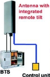
To be able to do this at ground level, antennas that have an integrated remote tilt allow a downtilt change via a control unit at the BTS. But due to the fact that the downtilt angles only have to be altered very rarely, these RET systems are not operated very frequently.
Future UMTS networks
GSM is based on the TDMA principle (time division multiple access). Each sector only handles certain frequencies and the cell size is fixed. UMTS in contrast, works using the WCDMA principle (wideband code division multiple access). This uses the full frequency band in each cell and is a dynamic network with changing coverage footprints. Contrary to GSM, UMTS will make use of remote-controlled adjustable electrical downtilt (RET) at a much higher level (60-80% of sites).
However the concept of remote control via an external control unit located near the BTS will not provide sufficient flexibility. Instead, a central control via the common OMC (operational maintenance centre) is required in order to deliver quick access with respect to the following situations:
Power control and cell breathing: The effective power levels for UMTS is relatively low. Therefore it is very important for an optimal running network to keep the power level within a certain variation. This is particularly difficult at the cell borders. In order to meet the requirements regarding the power level, the size of the cells can vary depending on the load of the cell (number of subscribers, transferred data rate). RET supports the power level adjustment by varying the coverage footprint.
Soft handover: With UMTS a certain percentage of all subscribers is under a permanent soft handover situation (covered by two or more cells); an estimation is 30-60%. Exact values are not available with respect to cell breathing. RET is able to support fine tuning during running operation.
Hot spots: In RET systems the network can be adapted to changing situations during the day, eg to cover increased capacity needs in specific places during rush hours.
Network extension: During the installation of a network and its adaptation to suit growing numbers of subscribers, the cells may have to be reconfigured to accommodate the ever-changing network plans. With RET these corrections can be made without having to send installation teams to the base stations.
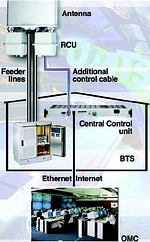
RCU (remote control unit)
Operators may be uncertain about the use of RET because the experiences in WCDMA network planning are still limited. Therefore Kathrein Werke designed a solution using a remote control unit (RCU), which is not integrated in the antenna, but offered as a retrofit option for antennas that have already been installed.
The RCU can be easily attached without dismantling the antenna and is suitable for operation under outdoor conditions. It is directly mounted at the bottom of all antennas that are equipped with an appropriate mechanical interface. The RCU contains a stepper motor which drives the downtilt spindle via gear as well as an electronic control for safe operation without data loss. The housing which is grounded via the antenna, is made of solid aluminium for excellent lightning and EMC (electro-magnetic compatibility) protection. Each wire of the control cable is also internally lightning-protected.
Controlling the RCU
The major component for the control of the RCU is the central control unit (CCU) which is located at the BTS. There are two possible inputs for the access from the OMC:
* RS232 - This input is used to configure the system with a laptop computer. After configuration it can be used to connect to the Internet (TCP/IP protocol) or modem.
* Ethernet - Connection via a WLAN network. The connection to the RCU is carried out via a 4-wire cable, two for the HDLC data and two for the +28 V power supply. Up to nine RCUs can be connected via splitters to one CCU.
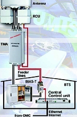
TMA - tower mounted amplifier
In most cases WCDMA will use TMAs to face the ever-increasing problems with site aquisition. TMAs can minimise initial investments and speed up roll-out since fewer sites are needed and a higher degree of flexibility with the site location is possible. The use of TMAs leads to enhanced coverage and improved voice quality, resulting in fewer dropped calls and an increase in revenue.
An elegant way of control is to combine a TMA and an RCU. The control signal and DC power supply are fed onto the RF-cable via a Smart Bias-T. The TMA decouples both and feeds the individual RCUs. The operator hereby saves on cable and has a professional solution from one supplier. Kathrein TMAs are available with this optional feature.
UMTS is the future standard. It remains to be seen how the scenario will pan out. With respect to power control, cell breathing, soft handovers, hot spots and network extension, Kathrein-Werke is optimally positioned with the RET system to provide professional antenna solutions.
(Article supplied by Grintek Antennas, 012 674 3500, [email protected])


© Technews Publishing (Pty) Ltd | All Rights Reserved
 printer friendly version