


Ref: z263142m
Better efficiency, reduced size, and lower costs have combined to make the switching regulator a viable method for converting unfiltered DC input voltages into regulated DC outputs. This article by Magnetics describes the switching regulator and presents design information. In particular, Magnetics Ferrite and Molypermalloy Powder cores used for the power inductor are highlighted.
Description
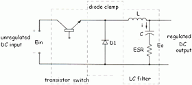
A typical circuit consists of three parts: transistor switch, diode clamp, and an LC filter. An unregulated DC voltage is applied to the transistor switch which usually operates at a frequency of 1 to 50 kHz. When the switch is ON, the input voltage, Ein, is applied to the LC filter, thus causing current through the inductor to increase; excess energy is stored in the inductor and capacitor to maintain output power during the OFF time of the switch. Regulation is obtained by adjusting the ON time, ton, of the transistor switch, using a feedback system from the output. The result is a regulated DC output, expressed as:
Eout = Ein ton f (1)
Component selection
The switching system consists of a transistor and a feedback from the output of the regulator. Transistor selection involves two factors-: (1) voltage ratings should be greater than the maximum input voltage, and (2) the frequency cutoff characteristics must be high compared to the actual switching frequency to ensure efficient operation.
The feedback circuits usually include operational amplifiers and comparators. Requirements for the diode clamp are identical to those of the transistor. The design of the LC filter stage is easily achieved. Given (1) maximum and minimum input voltage, (2) required output, (3) maximum allowable ripple voltage, (4) maximum and minimum load currents, and (5) the desired switching frequency, the values for the inductance and capacitance can be obtained. First, off-time (toff) of the transistor is calculated.
toff = (1 - Eout/Ein max)/f (2)
When Ein decreases to its minimum value,
Fmin = (1 - Eout/Ein min )/toff (3)
With these values, the required L and C can be calculated.
Allowing the peak to peak ripple current (Δi) through the inductor to be given by
Δi = 2•lo min (4)
the inductance is calculated using
L = Eout toff/ΔI (5)
The value calculated for Δi is somewhat arbitrary and can be adjusted to obtain a practical value for the inductance.
The minimum capacitance is given by
C = Δi/8f min Δeo (6)
Finally, the maximum ESR of the capacitor is
ESR max = Δeo/ΔI (7)
Inductor design
Two different types of core materials are commonly used for the inductor in a switching regulator - powder cores and ferrite cores. It is difficult to recommend one material over the other since the designer must take into consideration factors such as cost, volume, size and space limitations, and winding capabilities. Each material type has advantages as described below.
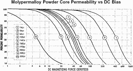
Magnetics powder cores have a distributed air gap structure, making them ideal for switching regulator applications. This structure gives a soft saturation characteristic that has many design benefits, including an overall smaller core size, and overcurrent protection. It also alleviates the fringing flux difficulties that occur if a discrete gap design is used. The DC bias characteristics of powder cores allow them to be used at high drive levels without saturating. They are available as toroids in three different materials: Molypermalloy (catalog MPP-400), High Flux (catalog HFC-1.1), and Kool Mu (catalog KMC 2.0). E-core shapes are also available in Kool-Mu material (bulletin KMC E1). A wide range of sizes and permeabilities exists to meet the needs of diverse applications.
Ferrite cores offer the advantages of decreased cost and low cores losses at high frequencies. For switching regulators, power ferrite materials (F, P, R, and K) are recommended because of their core loss and DC bias characteristics. By adding discrete air gaps to these ferrite shapes, the cores can be used efficiently while avoiding saturation. Magnetics produces many sizes and shapes to suit a variety of needs. Hardware is also available for most parts. Detailed descriptions are covered in Magnetics' Ferrite Cores Catalog FC-601.
Core selection procedure
These core selection procedures simplify the design of inductors for switching regulator applications.
For powder cores:
One can determine the smallest core size, assuming a maximum decrease in inductance of 50% and wire current carrying capacity of 500 circular mils per ampere.
Only two parameters of the design application must be known:
(1) Inductance required with DC bias,
(2) DC current.
In this article, Molypermalloy Powder Cores are featured in the examples. However, this design procedure can be used for any of the powder core types, including the Kool Mu E-cores. Simply refer to the design charts and data within those catalogues for the material and shape of choice.
1. Compute the product of LI² where:
L = minimum inductance required with DC bias (millihenries)
I = maximum DC output current = I0 max + Δi.
2. Locate the LI² value on the Core Selection Chart.
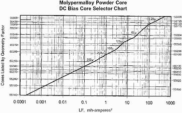
The Molypermalloy DC bias Core Selector Chart (see Charts below) will quickly yield the optimum permeability and smallest core size for most switching regulator applications. This chart is based on a permeability decrease of no more than 50% with DC bias and typical winding factors of 40%. Follow this coordinate to the intersection with the first core size that lies above the solid permeability line. This core size is the smallest that can be used.
3. The optimum permeability for that coordinate can also be read from the solid permeability line. For most applications with a given LI² value, the permeability indicated will result in the smallest core size possible. This is due to the tradeoff between the quicker DC bias rolloff of a higher permeability core versus the additional windings that would be necessary for a lower permeability core.
4. Inductance, core size and permeability are now known. The AL (millihenries per thousand turns) can be obtained from catalogue MPP-400. With this information, calculate the number of turns needed to obtain the required inductance. This number will then have to be adjusted for the DC bias roll-off. The procedure for this adjustment is described within each of the Magnetics powder core catalogues.
5. Choose the correct wire size using the Wire Table located within the catalogue.
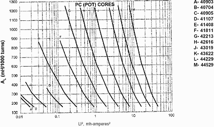
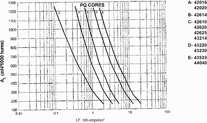
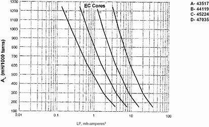
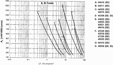
For ferrite cores:
1. Compute the product of LI² where:
L = minimum inductance required with DC bias (millihenries)
I = maximum DC output current = l0 max + Δi.
2. Locate the LI² value on the Ferrite Core Selection charts below (also located in the Magnetics Ferrite Cores Catalogue FC-601). Follow this coordinate to the intersection with the first core size curve for the ferrite shape of choice. Read the maximum nominal inductance (AL) on the Y-axis. This represents the smallest core size and maximum AL at which saturation will be avoided.
3. Any core size line that intersects the LI² coordinate represents a workable core for the inductor if the core's AL value is less than the maximum value obtained from the chart. It is important to remember that the AL value for a gapped ferrite core comes with a tolerance range, and therefore the high end of the tolerance range should be noted to ensure that it is not higher than the AL value obtained from the chart.
4. Required inductance L, core size, and core nominal inductance (AL) are known.
Calculate the number of turns using:
N = 1000 (L/AL)½ Where L is in millihenries.
5. Choose the wire size from the wire table in Catalogue FC-601 using 500 circular mils per amp.
Choosing a powder core material
While Molypermalloy and ferrite cores are featured in this brochure, Magnetics Kool Mu and High Flux powder cores are also excellent for inductor applications. Kool Mu cores offer an economical advantage over all three types. The Kool Mu Ecore shape may be chosen over the traditional toroidal powder core shape for ease of winding considerations. High Flux cores offer the most energy storage capability, resulting in the smallest possible core size when saturation is the limiting factor. Molypermalloy cores offer the widest selection and have the lowest core loss of any powder core. Depending on specific circuit requirements, temperature considerations, etc, size and other advantages of one type over others may be realized. A detailed LI² chart for Molypermalloy cores appears below; the LI² graphs for High Flux and Kool Mu toroid cores are shown in their respective catalogues. For more information, refer to the appropriate catalogue.
Design example
Choose a core for a switching regulator with the following requirements:
Eo = 5 V
Δeo = 0,5 V
Io max = 6 A
Io min = 1 A
Ein min = 25 V
Ein max = 35 V
f = kHz
1. Calculate the off-time and minimum switching, fmin, of the transistor switch using equations 2 and 3.
toff = (1 - 5/35)/20000 = 4,3 x 10⁻⁵ s and
fmin = (1 - 5/25)/4,3 x 10-5 s = 18 700 Hz.
2. Let the maximum ripple current, ΔI, through the inductor be
Δi = 2 (1) = 2 A
by equation 4.
3. Calculate L using equation 5.
L = 5(4,3 x 10⁻⁵)/2 = 0,107 millihenries
4. Calculate C and ESR max using equations 6 and 7.
C = 2/8 (18 700) (0,5) = 26,7 µF and ESR max = 0,5/2 = 0,25 Ω
5. The product of LI² = (0,107) (8)² = 6,9 millijoules
For Molypermalloy powder core design:
6. Locate the LI² value of 6,9 millijoules on the Core Selector Chart. Following this value to the intersection with the first core size that lies above the permeability line gives a core size number of 55585. (Note that part numbers in this chart are referenced to 125 µ).
7. The 6,9 coordinate falls in the 60 µ section. The 60 µ core that is the same size as the 55585 core is the 55586-A2 core (see the Molypermalloy Powder Cores catalogue MPP-400).
8. The 55586-A2 core has a minimum inductance of 34,96 mH/1000T (nominal inductance is 38 ±8% mH/1000T). The number of turns needed to achieve a minimum of 0,107 mH without considering DC bias is 1000•(0,107/34,96)½ = 56.
9. Powder cores have the property of soft saturation. This has the effect of gradually decreasing the permeability (inductance) with increased DC bias current. Therefore, to achieve the minimum inductance of 0,107 mH at the specified DC bias of 8 A, additional turns will be required. The procedure for determining the additional number of turns is explained in each of the Magnetics Powder Core catalogues. Using this procedure, the final number of turns required when considering the DC bias condition is 68.
10. Using 500 circular mils/amp, this gives a wire size of AWG 14.
A 55586-A2 core with 68 turns of AWG 14 wire meets the design requirement.
For ferrite core design:
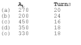
6. Due to the many shapes available in ferrites, there can be many choices for the selection. Any core size that the LI² coordinate intersects can be used if the maximum AL is not exceeded. Following the LI² coordinate, five of the available choices are:
(a) 43230 (PQ core) AL 270
(b) 43622 (pot core) AL 200
(c) 44229 (solid centrepost core) AL 450
(d) 45015 (E core) AL 350
(e) 45224 (EC52 core) AL 330
7. Given the AL, the number of turns needed for the required inductance is:
8. Using 500 circular mils/amp, this gives a wire size of AWG 14.
Charts
The Ferrite DC bias core selection charts
Lawrence Pinnoy, 011 403 3420, [email protected]


© Technews Publishing (Pty) Ltd | All Rights Reserved
 printer friendly version