


IoT devices are typically small and often have a severely limited power budget to operate for long periods from a small energy source such as a primary coin cell. While careful selection of ICs and modules, taking advantage of low-power operating modes, can help to save circuit footprint and reduce energy demand, things are often not so simple around the radio-frequency (RF) components, and the antenna in particular.
An antenna that may be suitable on paper is not guaranteed to perform well in practice. Proper selection and design-in are both essential to ensure a reliable wireless connection, covering the desired communication distance, while driving the antenna at the lowest possible input power to minimise demand on the device’s precious energy supply.
Antenna selection
The antenna is subject to the laws of electromagnetics and so must meet certain physical criteria to resonate at the desired frequency. This may be a frequency in an unlicensed band, such as 2,4 GHz for Bluetooth, Zigbee, Wireless Hart, or Thread devices, 2,4 GHz or 5 GHz for Wi-Fi, or a sub-GHz frequency as used in Low Power Wide Area Network (LPWAN) technologies such as LoRa or Sigfox. Alternatively, the device may have a cellular IoT connection such as LTE-M or NB-IoT operating in a band above or below 1 GHz, depending on the region.
The antenna for a small, high-frequency wireless device can be as simple as a PCB trace or a bent wire. The effective length in relation to the target RF signal wavelength is critical: a large antenna may offer superior range at the cost of demanding more space; on the other hand, a smaller antenna may fit the device’s form factor at the cost of shorter range or increased power demand. Those in the know can employ many tricks to achieve the desired communication range with an acceptable energy demand, size, and shape.
In addition, with the widespread adoption of contactless technology for mobile payments, near-field communication (NFC) is increasingly likely to be found in small IoT devices for various consumer and industrial applications. Providing a fast and convenient means of connecting to share credentials or authenticate devices, NFC’s 13,56 MHz operating frequency typically requires a coiled loop antenna.
Many engineering organisations do not have specialist RF designers in-house and would need to rely on external consultants to create an optimised antenna design. An alternative is to work with the antenna design service of a trusted supplier. Avnet Abacus has close links with antenna manufacturers including AVX, Molex, and Pulse Larsen, which provide expertise and processes to help IoT device designers overcome antenna-related challenges. These services are ready to help customers fulfil their design goals using standard, off-the-shelf antennas or by creating a custom solution if needed. Using an off-the-shelf antenna can ensure a faster turnaround time and deliver a competitively priced solution.
To choose an antenna, the search can be focused according to frequency range or wireless standard. Antennas are available for single-band applications or multi-band antennas designed for multiple feeds.
Depending on various mechanical factors, such as the PCB size, the size and shape of the enclosure, and the intended operating environment, the embedded surface-mount antennas, edge-mounted PCB antennas, cable antennas, and external antennas are the most commonly used. On-metal cable antennas are also available, which are designed to allow mounting directly on a metal surface without compromising RF performance.
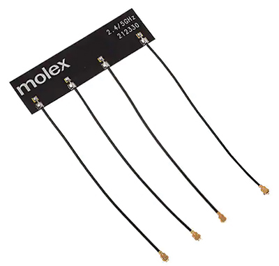
Molex has a selection of flexible cable antennas for various applications such as Bluetooth/Zigbee and Wi-Fi, including multiple-input/multiple-output (MIMO) antennas that support the latest-generation Wi-Fi 6E specification (Figure 1). Various choices of cable and connector types are offered to suit customers’ applications, and the antennas are treated with double-sided adhesive to aid fast and easy assembly.
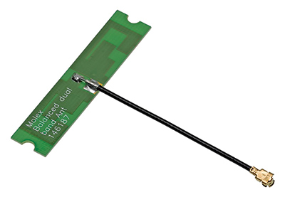
On the other hand, cable-mounted rigid PCB antennas can be attached to a convenient surface, such as a chassis part or the inside of an enclosure. The Molex 2,4 GHz/5 GHz balanced PCB antenna shown in Figure 2 is supplied with ready-made screw holes to allow convenient fixing.
Stamped metal antennas are also widely used and can be designed for direct attachment to the PCB or for off-board use. These are particularly well suited to high-speed, high-volume assembly and can offer superior performance, including increased range and coverage, compared to low-temperature co-fired ceramic (LTCC) antennas.
Ready-to-use NFC antennas are typically made of a flexible material to stick on almost any substrate and allow easy electrical connection to pogo pins or spring clips. Molex rectangular NFC antennas in various sizes from 15 mm x 15 mm to 45 mm x 55 mm optimise size and ensure easy, reliable wireless connections. An optional ferrite layer enhances performance when placed on a metallic substrate.
Design-in affects performance
The performance of any antenna is always influenced by the nearby surroundings – in particular, metallic components such as a heatsink or EMI shielding, a battery or large capacitor, high-speed digital PCB traces, power components, or ground connections. A ‘keep-out’ area is usually needed to ensure none of these encroach on the antenna’s near field. If size constraints on the main PCB preclude an adequate keep-out area, a cable mounted antenna can be considered. It may be soldered directly to the PCB or attached using a micro-coaxial connector.
The effects of the enclosure must also be considered, including the type of material, special surface treatments such as metallisation, and its proximity to the antenna. Factors outside the designer’s control can also influence antenna performance, such as when operated close to human body tissue in a wearable application.
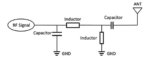
To ensure proper electrical integration of the antenna, the impedances of the antenna and the RF amplifier output should be matched for optimum power transfer. Although the antenna impedance is quoted on the datasheet, nearby components on the circuit board and the material properties of the device enclosure can introduce additional loading effects. A matching network may be needed to compensate, which can be a simple series capacitor and parallel inductor for a single-band antenna, or a more complex network for a dual-band application (Figure 3).
Because so many factors associated with the antenna design and performance are application dependent and can be mitigated to a greater or lesser extent by designers’ decisions, the parameters quoted in the antenna datasheet – such as impedance, gain and efficiency – should be viewed only as a guide to the likely performance in practice. Testing is recommended throughout the development cycle to validate antenna selection and ensure that any subsequent design changes do not impair its performance.
Start early
With these issues in mind, antenna selection and design should be considered as early in the product development cycle as possible. Testing RF performance early is recommended, at a stage where the PCB layout can be revised if necessary without excessive expense.
Changes may be needed to enlarge the antenna keep-out area, or to reposition the antenna away from influencing components, or to select alternative components or materials to be used for the antenna. Conversely, tests on early prototypes may show that RF performance can be achieved more easily than expected, allowing a smaller keep-out area or closer component spacing to ease other aspects of the product design.
Conclusion
An off-the-shelf antenna can offer a fast and cost-effective way to overcome the wireless design challenges of small IoT devices. On the other hand, the positioning relative to other components, the electrical connection, and matching circuitry are specific to the application and the operating environment.
Considerable design effort might be needed to achieve the desired performance.
Getting help to select a suitable antenna and arrange the near-field environment to minimise interference is recommended. Starting as early as possible in the project is essential, to avoid complicated and expensive changes to the product layout and PCB design at a later stage. If you’d like to discuss your design, contact our technical specialists at www.avnet-abacus.eu/ask-an-expert
| Tel: | +27 10 447 0180 |
| Email: | [email protected] |
| www: | www.avnet.com/wps/portal/abacus |
| Articles: | More information and articles about Avnet Abacus |


© Technews Publishing (Pty) Ltd | All Rights Reserved
 printer friendly version