


Electrical signal chains can be found in various forms. They can consist of different electrical components, including sensors, actuators, amplifiers, analog-to-digital converters (ADCs), digital-to-analog converters (DACs), or even microcontrollers. The accuracy of the overall signal chain plays a decisive role. To increase the accuracy, it is first necessary to identify and minimise the respective errors in the individual links. Depending on the signal chain complexity, this analysis can turn into a daunting task.
This article presents a precision DAC signal chain error budget calculation tool. It will describe the individual error contributions of the components connected with DACs. Finally, it will demonstrate step by step how this tool can be used to identify and correct these issues.
A precision DAC error budget calculator is precise, easy to us, and can help developers select the most suitable component for a particular application.
Because DACs do not usually appear alone in the signal chain, but instead are connected to voltage references and operational amplifiers (as reference buffers, for example), these additional components and their respective errors must be considered and summed. To better understand this concept, we first look at the individual error contributions of the main components, as shown in Figure 1.
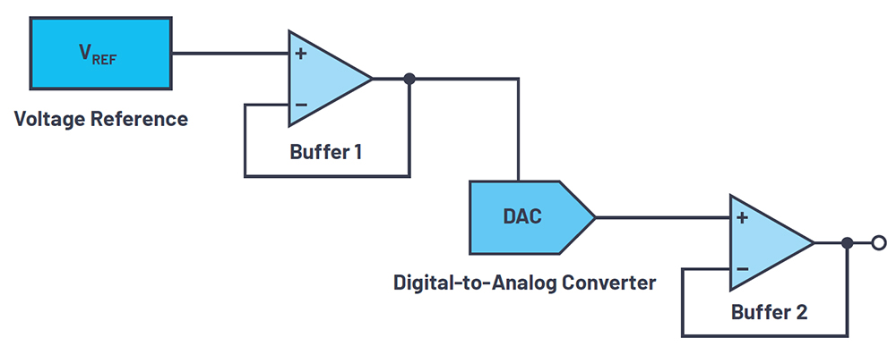
The voltage reference has four main error contributors. The first is associated with the initial accuracy (initial error), which indicates the variation in output voltage as measured in production tests at a defined temperature of 25°C. Added to that are the errors related to the temperature coefficient (temperature coefficient error), load regulation errors and line regulation error. The initial accuracy and temperature coefficient error contribute the most to the total error.
In op-amps, the input offset voltage error and the tolerance error of the resistors have the greatest effect. The input offset voltage error refers to a low differential voltage that must be applied to the inputs to force the output to 0 V. The tolerance error of the resistors is the gain error caused by the corresponding tolerances used for setting the closed-loop gain. Other errors are caused by the bias current, the power supply rejection ratio (PSRR), the open-loop gain, the input offset current, the CMRR offset, and the input offset voltage drift.
For the DAC itself, various types of errors are given in the data sheet – for example, the integral nonlinearity (INL) error, which relates to the difference between the ideal output voltage and the output voltage measured for a given input code.
Further types are the gain, offset and gain temperature coefficient errors. These are all sometimes grouped together to form the total unexpected error (TUE). This relates to the measurement of the output error in consideration of all DAC errors – that is, the INL, offset and gain errors, as well as the output drift over the supply voltage and temperature.
Since the different sources of error are usually not correlated, the most precise approach for calculating the total error in the signal chain is the root sum square method:
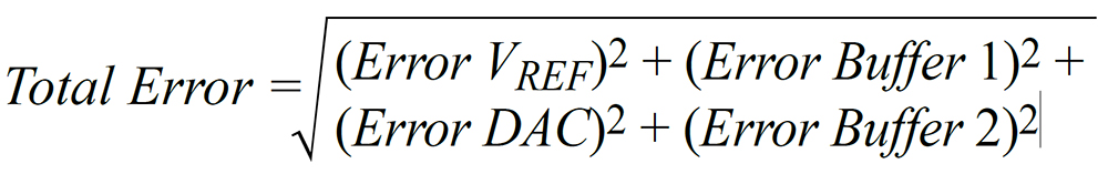
Collecting the errors of the respective components is usually a tedious task, so we can simplify this with the error budget calculator to derive an equally precise calculation.
Using the precision DAC error budget calculator, step by step
First, using Analog Devices’ error budget calculator https://beta-tools.analog.com/DACErrorBudget/, make a selection from three DAC types: voltage output DAC, multiplying DAC and 4 to 20 mA current source DAC. Next, set the desired temperature range and the supply voltage ripple for the error calculation.
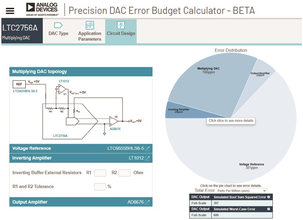
The latter is decisive for the PSRR error. Once these values are entered, the calculator generates a chart showing the respective error contributions of the individual components in the signal chain, as shown in Figure 2. The total error in this example is mainly influenced by the voltage reference. An improvement in this signal chain could be achieved through use of a more precise reference module.
The DAC’s integrated resistors, which are responsible for the comparison of the internal inverting amplifier and thus for an improvement in the accuracy, make a decisive contribution to the total error of the DAC. In DACs without integrated resistors or an internal inverting amplifier, these parameters can be specified separately, as shown in Figure 2.
The error budget calculator is reliable and simple to use, making it easier to create the precision DAC signal chain and to quickly evaluate design trade-offs.
For more information contact Conrad Coetzee, Altron Arrow, +27 11 923 9600, [email protected], www.altronarrow.com


© Technews Publishing (Pty) Ltd | All Rights Reserved
 printer friendly version