The ability to cut the cord and take the power of technology with us wherever we go (or even places we don’t go) is undeniably one of the greatest technological advances of all time.
Our needs have evolved since the first battery was invented. We were once concerned with keeping train cars illuminated while the engine was shut down for refuelling. Today, we seek smartwatches and fitness trackers that run for weeks without a source of energy. We seek industrial robots and automatic guided vehicles (AGVs) that can stock shelves, deliver packages and even sanitise hospitals with minimal downtime. As our needs evolve, so too must our engineered solutions.
An obvious area of development and innovation to meet these evolving needs is in battery technology itself: developing battery cells and modules that store more energy in smaller packages, and that withstand harsher environmental conditions. But improving the means by which we use and convert energy is equally as important as improving the means by which we store it. The battery in your smartwatch wouldn’t last through your morning jog if someone hadn’t thought hard about how to effectively utilise the energy stored in its battery.
For a given battery selection and application, there are several downstream design decisions that can have a drastic impact on how long the battery lasts between charges or replacements. In this article, we’ll take a deeper look at some of the challenges today’s battery-powered devices are facing, and the pivotal power system design decisions surrounding how we convert and use stored energy to maximise device run-time.
Foundational concepts
Before we dig into design optimisation, let’s brush up on a few key concepts that will illuminate some of the challenges battery-powered devices face, and will drive the optimisation approach.
Conservation of energy
Run-time of our battery-powered designs is ultimately constrained by one of nature’s most fundamental physical laws: the law of conservation of energy. This law essentially tells us that the amount of energy in an isolated system is fixed. Within such a system, energy can be converted from one form to another, but it cannot be created or destroyed. Between charges or battery replacements, we have a fixed energy budget that is established by the physical constraints of the battery itself, and it is incumbent upon us to be frugal if we are to make that budget last.
Every battery-powered device has one or more intended or desired functions; the jobs or tasks the device has been designed to complete. Those tasks require energy to perform, but so do many of the prerequisite upstream support functions. Energy must be spent gathering data from the environment to support the execution of the task, and ‘thinking’ about how and when to perform the task.
Often, we must convert energy from one form to another several times before the chemical energy from a battery can become the mechanical energy of a robot, or the light energy leaving a display panel. Even the process of converting energy costs energy. In the case of AGVs and industrial robotics designed to deliver some payload, energy must also be spent ‘delivering’ the sensors, processors, power converters and mechanical parts that comprise the AGV itself. This concept is depicted in the energy flow diagram of Figure 1.
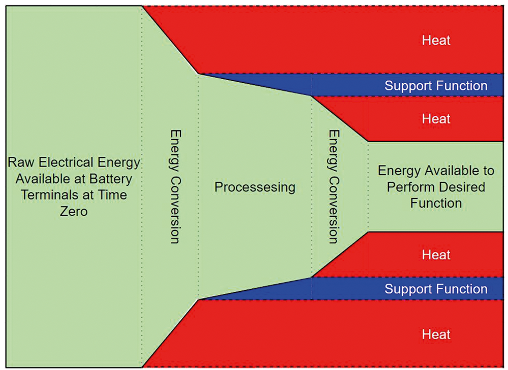 Figure 1. Representative energy usage in a generic system.
Notice that the total amount of energy in the system is the same on the left of Figure 1 as it is on the right, but some of that energy has been used to do something other than the directly intended function, and a good deal of it has been converted to heat (dissipative losses). To maximise the energy available to perform the desired function, one must minimise the energy lost during conversion (improve conversion efficiencies) and minimise the energy consumption of support functions.
Once steps have been taken to get as much energy as possible to the desired function, one can optimise the usage of that energy. To do so, it is important to understand the relationship between power, energy and time. This relationship is given in Equation 1:
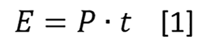
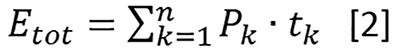
Equation 1 tells us that the amount of energy used performing a task is the product of the power required to perform that task (in Watts) and the amount of time for which it is being performed (in seconds). Equation 2 offers a generalised energy consumption model derived from Equation 1 for a system with ‘n’ operational modes or functions requiring different amounts of power. It follows naturally that if there are tasks requiring a lot of power, the design should be conscious about how long those tasks are performed for, spending as much time as possible in the lower-power states.
A simple battery model
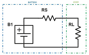
Batteries are not ideal power sources. Battery-powered designs face interesting challenges associated with the inherent variability of the source voltage-current characteristic at the battery terminals as the energy is gradually depleted. Figure 2 offers a simplified equivalent circuit model of a generalised battery.
The model of Figure 2 includes internal battery potential (B1), an internal source resistance (RS) and an external load (RL). RS is not fixed. Generally, this internal resistance is expected to increase as state of charge (SoC) decreases, and as the battery ages. RS can also vary significantly with temperature. As RS increases, the load voltage, maximum available current and maximum available power will all decrease.
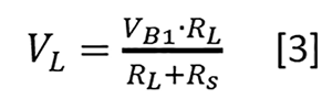
Equation 3 describes the voltage available to the load at the terminals of the battery as a function of the internal resistance:
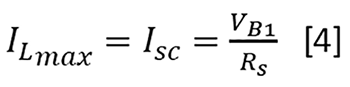
Equation 4 describes the theoretical maximum current available to the load (maximum short circuit current) as a function of the internal resistance:
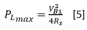
The maximum power transfer theorem tells us that maximum power is delivered to the load when the load resistance is equal to the source resistance. The maximum power available to the load can therefore be described as a function of the internal resistance. This relationship is given in Equation 5:
The variability in the voltage and current available at the battery terminals brings about the need for a well-optimised power conversion network to interface the energy source with the rest of the electrical design.
Design optimisation
Maximising the run-time of a battery-powered device is a multi-faceted engineering problem. Energy conservation must be at the forefront of every design decision. The design must include a highly efficient power conversion stage that effectively utilises the energy stored in the battery even as the available voltages and currents shift drastically with SoC, age and environmental conditions.
Careful consideration must be given to the specific performance requirements driving functional duty cycles to minimise the result of the energy model given in Equation 2. AGVs and other robotics designs face additional challenges. These devices must be small and lightweight to minimise the mechanical energy required for movement, and must often be designed to operate under harsh environmental conditions.
Power conversion topology
Selection of an appropriate power conversion topology is a critical first step in optimising a battery-powered design. This decision will impact the efficiency of the conversion stage, the input and output voltage ranges and the total weight of the power converter.
Linear power conversion will not provide the efficiency or input voltage range demanded by modern battery-powered applications. A switch-mode power converter must be deployed.
Most battery-powered applications will not require galvanic isolation between the primary and secondary sides of the switching power converter, as the primaries are not tied to the hazardous high-voltage mains. Selecting a non-isolated design, when possible, goes a long way in improving overall efficiency as there is no isolation transformer dissipating electrical energy as a result of hysteresis effects and eddy current generation in the core, as well as simple I2R losses in the windings, often augmented by the skin effect at higher switching frequencies.
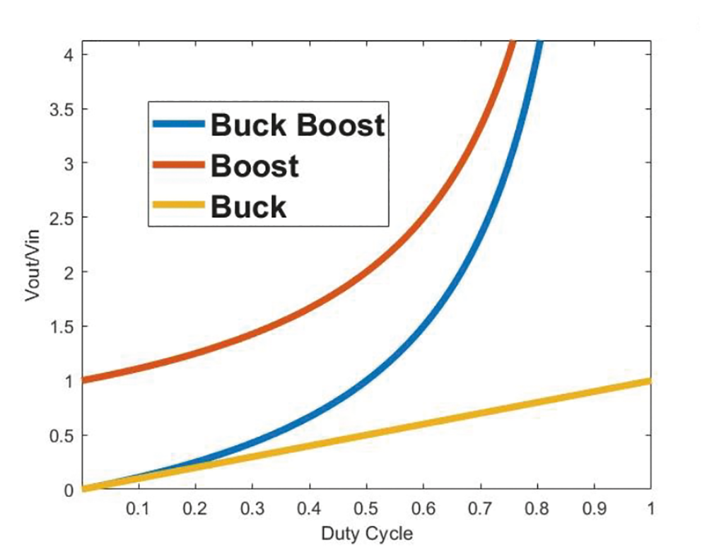
Because the voltage available at the terminals of the battery varies with SoC, age and ambient temperature, the power converter should be designed to allow for a wide-ranging voltage transfer function. Consider the normalised voltage transfer function of three popular conversion topologies depicted in Figure 3.
In examining Figure 3, one can see that the buck boost topology offers the widest-ranging transfer ratio. When battery SoC is high, the duty cycle can be adjusted below 33% to meet the needs of lower-voltage loads. As the terminal voltage depletes, the duty cycle can be adjusted above 33%, allowing for higher-voltage rails to remain energised. This sort of flexibility is particularly valuable in the design of modern industrial robotics, where battery module voltages could range from 1,5 V DC to as high as 60 V DC, and where sensor and motor loads demand supply voltages well outside of conventional silicon-tailored standards
The power converter should incorporate a good deal of bulk capacitance across the input. As the battery source impedance rises, available peak current falls. Having some low-impedance local energy storage at the input of the converter will help supply peak currents during load transients and keep the input rail from collapsing.
Conversion efficiency and quiescent consumption
Energy conversion is often responsible for most of the losses in a typical system. The DC-DC converter is the first bottleneck in the flow of energy from the battery to the load associated with the desired function. All energy that will be supplied to the load or used to support the desired function must first pass through this conversion stage. It is critically important to minimise the losses here. By deploying an appropriately sized, non-isolated switch-mode converter, a designer should be able to achieve conversion efficiencies exceeding 95%.
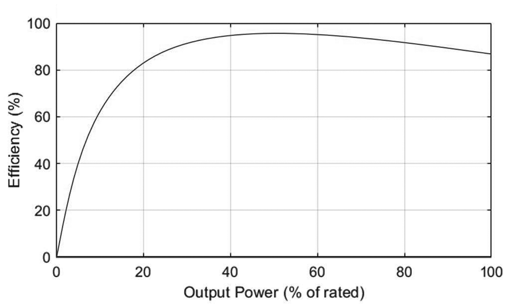 Figure 4. Representative power converter efficiency vs. load curve.
It is necessary to select a converter that is properly sized for the application, and to understand the efficiency vs. load characteristic. Figure 4 displays a generalised efficiency vs. load curve for a typical switch-mode power converter. Power converters are quite inefficient at light load (roughly less than 30% of rated power), where quiescent consumption dominates the loss profile. Above 80% rated load, it is typical to see efficiency start to drop again as I2R losses begin to take over the loss profile. Peak efficiencies will often be observed between roughly 40% and 80% of rated power.
Notice that conversion efficiency is 0% when a power converter is operated at 0% load. Even when output power is 0 W, some amount of power is drawn from the input to energise the control circuits and to maintain the output voltage, which may otherwise bleed off over time through parasitic impedances. The power drawn under these conditions is known as the quiescent consumption, a critical parameter in battery-powered designs.
If the device performance requirements have been carefully determined, it is not uncommon for most sub-circuits to spend a majority of their time in a quiescent state, waiting to perform some task quickly and efficiently. Consider the model for the average power lost by a conversion stage supplying varying amounts of power in ‘n’ operational modes given in Equation 6.
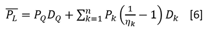
PL is the average power loss of the conversion stage in Watts, PQ is the quiescent consumption in Watts, DQ is the duty cycle of the quiescent state, Pk is the converter load in operational mode k, nk is the effective conversion efficiency in that state, and Dk is the duty cycle of that state. In examining Equation 6, it is clear that power loss is minimised by spending less time (lower duty cycle) in states with high Pk:nk ratios (not necessarily states with higher Pk). Also, given that it is not uncommon in a well-optimised design for DQ to be greater than D1,D2...Dn, the effective weight of PQ may be more significant than it seems at first glance.
In some cases, certain rail potentials need not be maintained in low-power sleep modes. In these cases, significant additional energy can be saved by inhibiting the supply rails to entire sub-circuits. Seeking a power converter with a logic-level ‘enable’ input can allow the system designer to turn quiescent sleep modes into deep sleep modes, capitalising on a large DQ.
Second-order effects
Optimising the power conversion design has several beneficial second-order effects above and beyond the direct impacts highlighted thus far. By deploying a non-isolated converter, the design can be stripped of large, heavy iron cores that contribute to the size and weight of the end-device. In some instances, a non-isolated converter in a 1/16-brick package can offer the same amount of power as a 1/4-brick isolated converter. With lighter power electronics, less mechanical power is required to move the end-device, resulting in additional energy conservation. Non-isolated converters can also have streamlined feedback loops, removing cost, complexity and a bit of quiescent load from the design.
Selecting a highly efficient converter reduces heat generation. Less dissipation allows designs to shrink and can open the door to more convenient cooling solutions. If convection or forced air cooling is deployed, less dissipation means smaller, lighter, lower-cost heatsink geometries. If total dissipation is low enough, a conduction cooling solution may even be feasible. Such a solution might be fundamentally required for applications deployed in harsh environments with a high potential for fluid or particulate ingress.
Summary
While it is imperative to select a suitable battery for your next battery-powered design, it is arguably just as important to optimise downstream electronics and power conversion stages to maximise the lifetime of the selected battery. Special attention should be given to the choice of topology, ensuring that as much of the battery’s output voltage range as possible is utilised, and minimising heavy magnetic elements that contribute to power loss at multiple levels.
Designers should seek conversion efficiencies exceeding 95%, and target designs that exhibit peak efficiencies in the load ranges that will most commonly be exercised. The impact of quiescent consumption should not be underestimated, and careful consideration should be given to asserted performance requirements, allowing devices to operate in low-power modes or even deep sleep power-inhibited modes as often as possible.
Consider partnering with an experienced power conversion design expert to address the needs of your next battery-powered design. Commercial off-the-shelf (COTS) solutions specifically tailored to AGVs and other battery-powered applications are available, such as the i7C series of four switch, non-isolated, wide-input, wide-output buck boost DC-DC converters from TDK-Lambda.
Equipped with a built-in standby feature to support deep sleep operation, i7C converters offer up to 300 W in a compact
| Tel: | +27 11 782 8728 |
| Email: | [email protected] |
| www: | www.accutronics.co.za |
| Articles: | More information and articles about Accutronics |


© Technews Publishing (Pty) Ltd | All Rights Reserved
 printer friendly version