


Extending battery life means increasing system performance, lengthening operating time, and decreasing costs. Typically, three of the ways to do this are by improving battery technology, designing better devices, and innovating energy management systems. Improving battery technology includes choosing the right battery for the specific application and designing the appropriate battery management system to control charging, regulate temperature, and minimise losses. Designing better devices involves the consideration of efficient hardware components and robust firmware, both of which are necessary to deliver an optimal balance of functionality and longevity. To intelligently optimise energy consumption, one can leverage the latest power management systems that employ AI-based algorithms, newer topologies, and efficient converter control methods such as PassThru mode and power-saving mode.
Understanding supercapacitors
Using energy storage devices, like supercapacitors, alongside batteries can benefit different use cases. The advantages include quick charging and discharging for short bursts of power, longer lifetime, and overall greater system efficiency. For example, supercapacitors are great for quickly storing energy and providing backup power. They can withstand extreme temperatures and conditions. When combined with batteries, as in electric cars, supercapacitors help improve performance and increase battery life. In addition, supercapacitors are better for the environment.
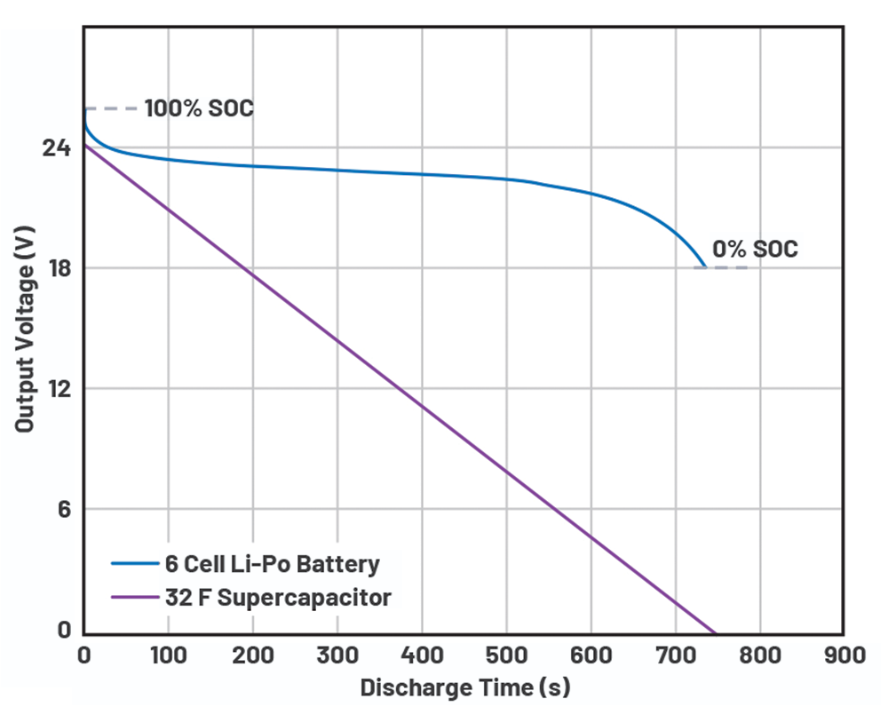
Figure 1 shows how a supercapacitor differs from a battery. With the same rated voltage, the six-cell, 0,1 Ah, Li-Po battery exhibits the characteristics of a voltage source as it provides a more stable voltage for its entire operation. In contrast, the voltage linearly drops as current flows from a 32 F supercapacitor to the load. Also, this linear discharge characteristic of supercapacitors requires more efficient systems to convert its energy. This is when the buck-boost converter’s functionality is most preferably used as it can properly regulate the output voltage whether the input voltage is below or above the output voltage setting.
What is PassThru mode?
PassThru technology is an essential feature for wide input-powered devices. It allows for improved efficiency and extends the lifespan of energy storage systems versus systems that utilise conventional control (standard buck-boost controller). Passthrough happens when, at a predefined voltage window, the input is passed directly to the output, as if it were acting like a shorted wire. PassThru technology acts as a network between the power source, such as a supercapacitor, and the load, ensuring voltage regulation at a specified acceptable range. It ensures that the device is running as efficiently as possible by providing a direct path from the power source to the load. PassThru mode is an important part of ensuring optimal efficiency in any supercapacitor-powered device, as it reduces the load/unload cycles of the supercapacitor, and improves EMI and the overall performance of the device.
How PassThru mode extends the life of an energy storage system
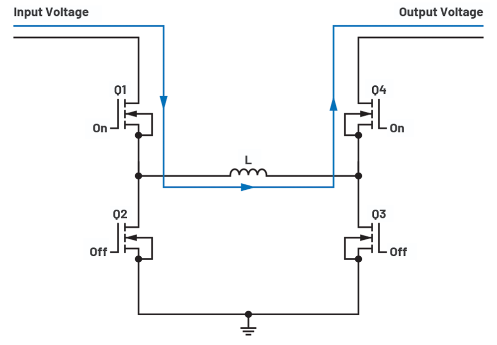
PassThru mode in four-switch buck-boost converters provides a direct path from the power source to the output load in accordance with a specified window setting as shown in Figure 2. The input is directly passed through to the output. This improves efficiency at the specified PassThru window by eliminating switching losses, and it also improves electromagnetic compatibility, as switching frequency does not occur in PassThru mode. PassThru mode in a buck-boost converter provides flexibility as it gives the option to set a different buck output voltage from the boost output voltage. This is contrary to typical buck-boost ICs that have only one nominal output voltage. This feature also protects the load when the input voltage behaves abnormally. PassThru technology is a mode of operation of the LT8210, which is currently the only buck-boost controller IC available in the market that has this capability.
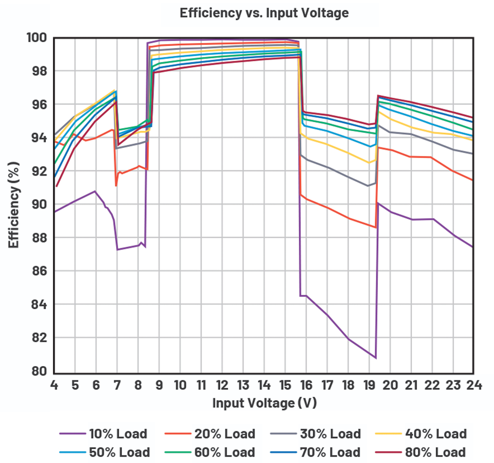
To get a glimpse of LT8210’s PassThru mode operation, one can refer to its data sheet or its demo board’s efficiency profile. Figure 3 shows the efficiency profile of the DC2814A-A demo board as swept from 4 V to 24 V input voltage and 10% to 80% load. Utilising the LT8210, this demo board operates from 4 V to 40 V input voltage, with a full load current of 3 A and an output voltage of 8 to 16 V. Operating in PassThru mode will increase efficiency by up to 5% in heavier loads and up to 17% in lighter loads such as with a 10% current load when referenced to the buck-boost operation. Thus, in light-load operating conditions, PassThru mode gives a significant improvement.
Notably, while the LT8210’s PassThru mode allows setting a different boost output voltage from buck output voltage, when the input voltage is around the output voltage setting, the buck-boost region appears. This buck-boost region present in LT8210 is due to the intersection of the buck and boost control regions with respect to one inductor current regulation.
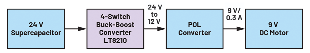
To understand the applied effect of PassThru mode, consider the system in Figure 4. The four-switch buck-boost converter is used as a pre-regulator to a point-of-load converter that is also used as a motor driver. While the power source is a 24 V supercapacitor, the DC motor requires an input specification of 9 V and 0,3 A. The buck-boost converter will either utilise PassThru mode or the conventional four-switch buck-boost control operating in continuous conduction mode (CCM). Note that the conventional buck-boost control does not have PassThru mode. It only has the buck, boost, and buck-boost operation as seen in Figure 3.
The system using PassThru mode has its boost output voltage set to 12 V while buck output voltage to 27 V. This allows the supercapacitor’s starting voltage within the pass band limits. Thus, the system will undergo PassThru mode from 24 V to 12 V supercapacitor voltage. During this time, the efficiency reaches 99,9%. Note that the converter will undergo buck-boost mode, resulting in a dip in efficiency before proceeding to boost mode. On the other hand, the system operating in the conventional buck-boost control has been set to operate with a constant output voltage of 16 V. This was done to set the output voltage around the midpoint of the pass band limits settings.
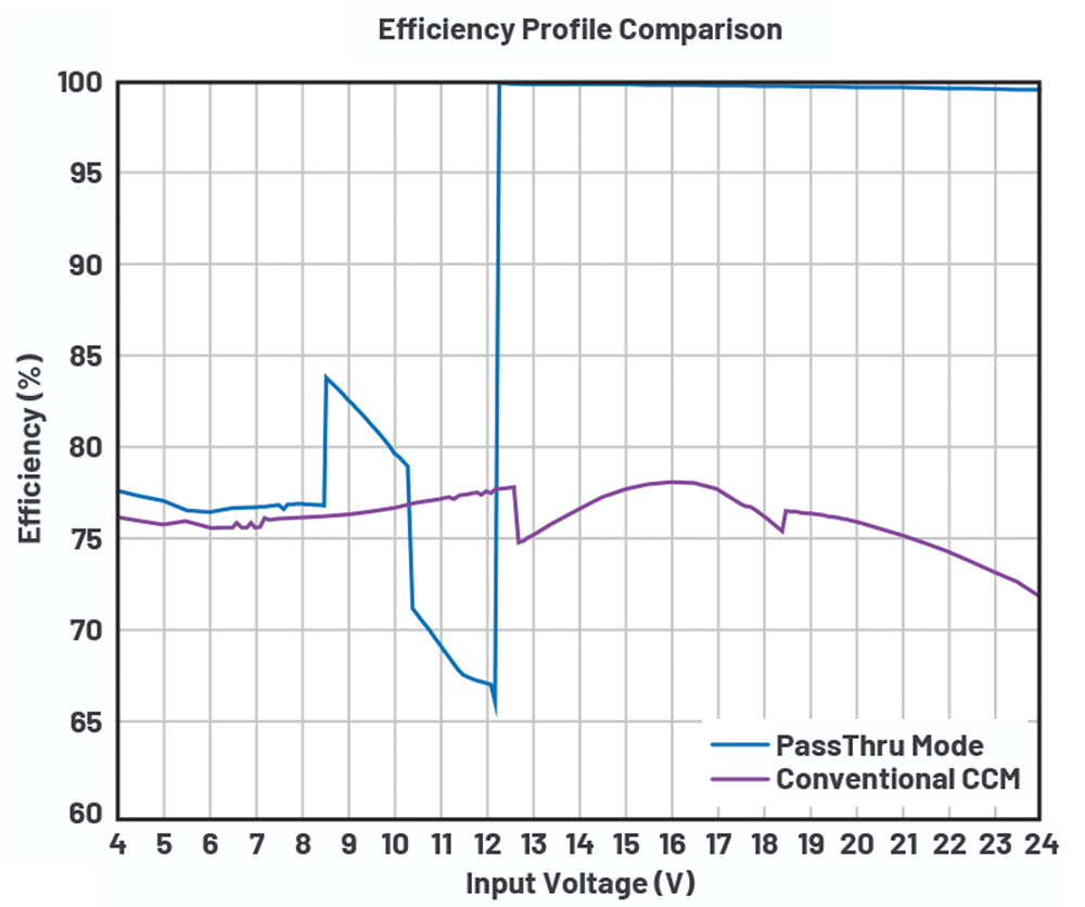
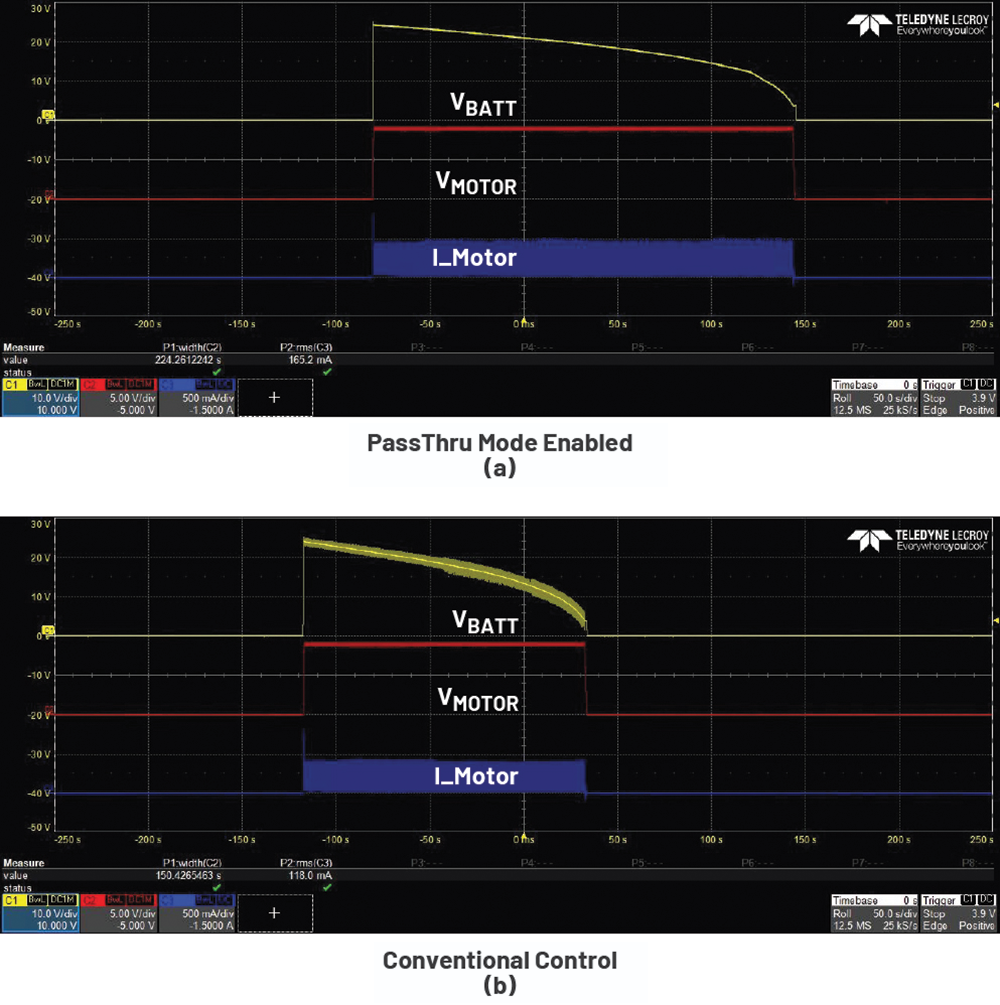
Figure 5 shows an efficiency comparison of the two buck-boost converters as the voltage is swept from 4 V to 24 V at 2,7 W. PassThru mode increased efficiency by 22% to 27% compared to the conventionally-controlled system. To further validate the difference of the two systems, they were tested with the battery emulator function of ITECH’s IT6010C-80-300. The following settings were used to emulate supercapacitor response with a run time of at least 120 seconds: starting voltage of 24 V, end voltage of 0 V, electric charge of 0,005 Ah, and internal resistance of 0,01 mΩ. Figure 6 shows the waveforms of the two systems. Channel 1 refers to the battery emulator voltage, Channel 2 refers to the motor voltage, and Channel 3 refers to the motor current. The PassThru controlled system operated for 224 seconds, whereas the conventionally controlled system operated for only 150 seconds. Thus, a 49% increase in operating time was observed for the system utilising PassThru mode.
Conclusion
PassThru technology is an important component for optimal performance in any supercapacitor-powered device. Utilising the LT8210 synchronous buck-boost controller equipped with PassThru mode can greatly optimise the efficiency of a supercapacitor-powered device when compared to a conventionally (CCM operated buck-boost) controlled system. In this example, PassThru mode enabled 27% more efficiency and increased the overall system’s total operating time, thus extending the energy storage system’s operating time by 49%.
| Tel: | +27 11 923 9600 |
| Email: | [email protected] |
| www: | www.altronarrow.com |
| Articles: | More information and articles about Altron Arrow |


© Technews Publishing (Pty) Ltd | All Rights Reserved
 printer friendly version