


The USB Power Delivery (PD) market continues to grow for portable, battery-operated, electronic devices like cell phones, laptops, wireless speakers, power tools, and more. USB PD provides a great benefit to consumers, because it can provide up to 240 W from the same USB Type-C connector.
USB PD poses new power requirement challenges because of the variety of voltage and current combinations available
Some solutions require multiple ICs, including port detectors, microcontrollers, and chargers for power delivery. While these solutions work, they take up space on a board, increase the solution cost, and require custom firmware, which can be time-consuming to create.
A standalone PD controller can help address these challenges by managing the power negotiations without firmware development.
USB-C PD power requirements
One of USB PD’s significant benefits is allowing consumers to charge a 2,5 W cell phone and a 25 W cordless power drill using the same cable and power adaptor.
Before we look at USB PD, however, we must revisit previous USB standards to understand some of the USB PD benefits and challenges. The first USB standards, USB 1.1 and USB 2.0, were for data delivery rather than power delivery. They only allow for a maximum delivery of 5 V and 500 mA across a USB cable.
Over time, consumers began demanding more from USB. They wanted to quickly charge a battery over a USB cable, where a 500 mA maximum current was no longer adequate. The BC1.2 standard answered these consumer demands by allowing the transfer of up to 7,5 W over a USB cable. This standard expands the ability to charge a battery over USB, and each new USB standard after BC1.2 has added to the power capacity. Type-C 1.3 extends the power capability to 15 W, while USB PD 3.0 upgrades the system wattage to 100 W (max). The most recent specification update, USB PD3.1, extends the power capability even further up to 240 W.
BC1.2 and Type-C 1.3 continue to supply the 5 V voltage rail used in all previous versions of the USB standard but have increased the power capabilities to 7,5 and 15 W, respectively. USB PD3.0 has also increased both the current and voltage capabilities to reach 100 W. It allows the transfer of up to 20 V and 5 A across a USB cable. The new PD3.1 specification supports up to 48 V and 5 A.
The voltage rails that a USB PD power source provides are variable. The USB PD 3.1 standard states that not only does a power source have to offer a minimum voltage of 5 V and a maximum voltage of 48 V, but it must also provide a few voltage rails in between.
The USB PD 3.0 standard requires that a power source provides specific voltage rails, depending on the power capabilities of the source. Sources that can provide more than 15 W must offer 5 and 9 V rails. Those that can provide more than 27 W must offer 5, 9 and 15 V rails. Finally, power sources that can provide more than 45 W must offer 5, 9, 15, and 20 V rails.
The power source also provides different current outputs at each of these voltage rails. A power source with a 5 V rail provides between 500 mA and 3 A at this rail. Those with a 9 V rail transfer currents between 1,67 and 3 A at 9 V. A power source supplies between 1,8 and 3 A at the 15 V rail and finally, the power sources provide between 2,25 and 5 A at 20 V.
The USB PD 3.1 standard adds three additional voltage rails for power sources. Sources provide fixed voltage rails at
In addition to the standard voltage and current supplies, the USB PD specification also provides a programmable power supply (PPS) capability. The PPS capability allows in-line devices to request small changes in voltage and current from the power source. This capability is most useful to speed up the charging of lithium-ion batteries by optimising the operating point for the switching charger.
USB-C PD design blocks
It is no small task for charging to begin under a discrete USB PD system. A power source, such as a wall adaptor, connects to the in-line device, such as a phone or power drill, through a USB cable. Both devices typically need multiple ICs to implement the back-and-forth communication to get the power source ready to provide the in-line device power (figure 2).
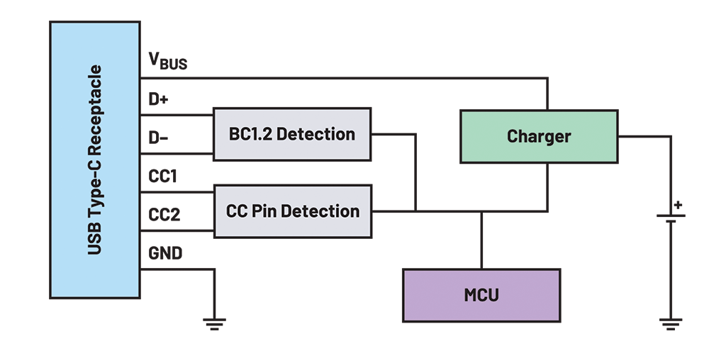 Figure 1. A USB PD design block diagram (courtesy Analog Devices).
The CC pin detection IC identifies the cable orientation and source current capability by measuring the voltage of the CC pins. This IC also requests the power source’s voltage and current capabilities and communicates back to the power source when the in-line device selects a voltage and current.
The BC1.2 detection IC supports legacy USB adaptors. Although newer devices are more widely adopting USB Type-C, many applications still use older USB specifications. BC1.2-compatible ports have D+/D– pins instead of CC pins to communicate a power source’s power capabilities. The BC1.2 detection IC reads the D+/D– pins to configure charging for applications still using legacy USB standards.
Finally, the microcontroller unit (MCU) block organises communication between the other ICs. The MCU communicates with the CC pin detection IC to determine the power capability of the power source. Then, the MCU compares the power source’s capability with the charger and battery’s power needs to determine how much current and voltage the power source should provide. The MCU communicates the final power settings back to the CC pin detection IC to configure the power source correctly. Once the correct current and voltage are confirmed, the MCU will configure and enable the charger.
Standalone PD controller
Standalone PD controllers can help simplify USB PD designs by having the CC pin detection, BC1.2 detection, and MCU integrated into one IC. The four-IC design now becomes just two, which saves board space and costs.
The most powerful element integrated into the standalone PD controller is the embedded MCU, which integrates all the USB PD 3.0 standard communication protocol and timing requirements. The designer no longer needs to spend development time coming up-to-speed on these specifications.
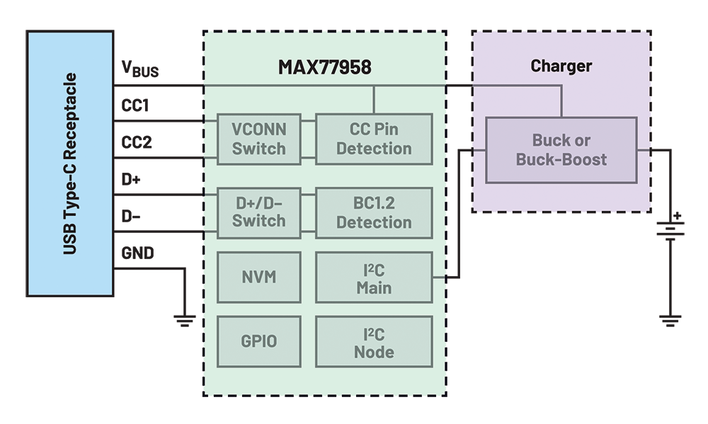 Figure 2. USB Type-C v1.3 and PD-compliant standaone PD controller (courtesy Analog Devices).
One example of a standalone PD controller is the MAX77958. Two unique features of the MAX77958 are the non-volatile memory and the I2C main port that directly controls a companion charger. Both features help eliminate the need for an external MCU and custom firmware development.
Designers can generate customised scripts for typical applications using a graphical user interface (GUI) and then load them into the non-volatile memory of the IC.
| Tel: | +27 11 923 9600 |
| Email: | [email protected] |
| www: | www.altronarrow.com |
| Articles: | More information and articles about Altron Arrow |


© Technews Publishing (Pty) Ltd | All Rights Reserved
 printer friendly version