


During the soldering process, the soldering iron tip undergoes physical changes which are a normal part of the process. These changes, over time, affect the ability of the soldering iron tip to make quality solder connections, and can decrease an operator’s performance. The key to maximising soldering iron tip life is understanding these changes and how to minimise them.
To understand the changes a soldering iron tip goes through during the soldering process, it is important to have a basic understanding of the construction of a soldering iron tip.
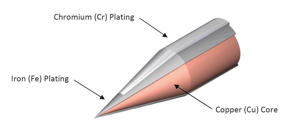 Figure 1. Soldering iron tip construction.
As shown in figure 1, most soldering iron tips have a copper (Cu) core that conducts heat energy from the heating element to the application being soldered. This core is protected with iron (Fe) plating that prevents corrosion of the core from the various components of the solder and flux being used in the soldering process. Iron is used due to its ability to conduct heat, and its chemical compatibility with the components of solder which allows the solder to flow from the tip to the soldering joint. An additional plating of chromium (Cr) is added to the tip, excluding its working surface, which protects the iron plating from corrosion.
There are two parts of this tip construction that are critical to the soldering iron tips life:
• Copper core.
• Iron plating.
These two parts of a soldering iron tip are directly affected by the following variables of the soldering process:
• Tip maintenance.
• Tip temperature.
• Solder.
• Flux.
• Operator technique.
• Soldering/rework application.
Tip maintenance
Maintenance of a soldering iron tip consists of regular cleaning, inspection, and the re-tinning of the tip’s working surface for protection. Proper tip maintenance is possibly the single largest contributor to extending tip life.
A soldering iron tip should be cleaned regularly by removing any oxidised solder, flux residue and debris from the tip. This can be done with a damp sponge or non-abrasive tip cleaner. If a sponge is used, be sure to use only distilled water on the sponge. If distilled water is not available or is too costly, de-ionised water may be used. The use of distilled or de-ionised water minimises any mineral contamination on the surface of the tip. It is also important to be sure to regularly replace the sponge since it will collect debris and other contaminants over time, and doing so will reduce the likelihood of reintroducing contaminants or debris to the tip.
A non-abrasive tip cleaner is an excellent alternative to using a damp sponge, since it minimises the thermal shock to the tip and does not remove all the solder from the end of the tip, which helps protect the plating of the tip from reacting with the surrounding air, which in turn leads to oxidation of the working surface and corrosion.
Most chemical tip cleaners, or ‘tip tinners’ should be avoided due to their aggressive cleaning properties, which is similar to highly active fluxes. These chemical tip cleaners may also leave residue that can build up, causing a blackening of tips and the oxidation of the plating. Gentle chemical tip cleaners, such as the Hakko FS-100 Tip Polish, may be used but only as supplemental cleaning aids.
During the cleaning of the tip, the condition of the working surface of the tip should be visually inspected for any signs of shape change, pin hole, or other physical defect. These are indications that the tip life has been consumed, and the tip should be replaced.
The final and most important part of tip maintenance is the application of solder to the tip’s working surface for protection, also known as ‘tinning the tip’. It is best to flood the entire working surface of the tip with solder immediately after cleaning. This process covers the working surface and protects it from reacting with the surrounding air which can lead to oxidation and corrosion.
Tip temperature
The selected temperature for a soldering iron tip affects tip life by accelerating the oxidation of the tip and the reaction of the solder and flux with the iron plating of the tip. Tip temperature also causes physical changes to the tip through the natural thermal expansion and contraction the metal undergoes during normal use.
In many cases, a common reaction to difficulties encountered in the soldering process, such as switching from tin-lead solder to lead-free solder, is to raise the tip temperature. This increases the rate of oxidation buildup on the tip and accelerates the reaction between the tin in the solder and the iron plating, corroding the tip faster. The added heat also increases the amount of thermal stress the metal undergoes. Using a lower tip temperature decreases the rate of oxidation, decreases the reaction between the tin in the solder and the iron plating, and lowers the thermal stress on the tip.
The most common affect tip temperature has on tip life is the acceleration of the reactions of the plating on the working surface of the tip, with not only the solder and flux that come in contact with the tip, but also with the surrounding air. At higher tip temperatures, these chemical reactions happen faster than at lower tip temperatures. The plating undergoes a chemical reaction with the components of the solder, namely tin (Sn), which over time will cause plating to wear away.
This can be seen on some tips as minor shape changes such as concave surfaces or smaller diameters when compared to new tips. The thickness, quality, and uniformity of this plating varies not only between tip manufacturers but in some cases, between tip shapes. Once the plating is worn thin enough, exposing the core of the tip directly to the solder, tip failure has occurred, and corrosion of the copper core happens rapidly. Using lower tip temperatures decreases the rate of this chemical reaction between the plating and the components of the solder.
Most high-end soldering stations in the industry today recognise this, and as a result, have built into their soldering station design the ability for the soldering station to reduce the soldering iron temperature when it is not being used by the operator. This ‘sleep’ mode slows the reaction between the plating and the components of the solder that is on the tip, and slows the rate of oxidation buildup. These high-end soldering stations sometimes include a feature that will automatically turn off the soldering station if it has not been used over a period of time. Whether or not you have a high-end soldering station, you should always reduce tip temperature when the soldering station is idle, and turn it off if it is not going to be used for some time. Doing so will decrease the rate of the chemical reaction between the plating and the components of the solder, and reduce the buildup of oxidation on the working surface of the tip.
The plating also undergoes a chemical reaction with the flux being used. This reaction is what you would expect from flux, but instead of cleaning the surfaces of the connection to be soldered, the flux is cleaning the working surface of the tip. This ‘cleaning’ also wears away the plating of the tip to a small degree. However, in this case, higher tip temperatures result in a faster burning of the flux, which results in deposits that are left on the surface of the tip. These deposits, if not cleaned off the surface of the tip, can build up over time, causing blackened tips and the exposure of the plating of the tip to the surrounding air, which leads to oxidation of the working surface and corrosion. This oxidation and corrosion is also accelerated by higher tip temperatures. Using a lower tip temperature reduces the buildup of deposits, the blackening of tips, and slows the reaction of any exposed iron plating with the surrounding air.
In older-technology soldering stations, the tip is inserted over a heating element. Over time, the thermal expansion and contraction of the metal in the tip core can cause air gaps between the core of the tip and the heating element when the tip is installed. These air gaps decrease the tip’s ability to conduct heat energy away from the heating element, causing lower tip temperatures. The higher the selected tip temperature, the more thermal stress the metal undergoes, which can lead to the faster formation of air gaps between the tip core and heating element.
Solder
The composition of the solder being used affects tip life through the reactions between the plating of the tip and the components of the solder. Solders that have high levels of tin (Sn), and other components that react with the plating, will shorten tip life. A clear example of this can be found in the industry switch from tin-lead solder to lead-free solder. While the selection of solder being used likely cannot be changed as easily as selected temperature, it is important to understand that any change in solder composition can affect tip life.
Flux
The flux being used in the soldering process, either in the wire core, or applied separately, affects soldering iron tip life to a small degree through the reaction between the plating of the tip and the activators in the flux. Fluxes that are highly active have a more aggressive cleaning action and are more aggressive in wearing away the plating from the tip. Using mildly active fluxes and/or less flux in the soldering process will reduce the wear on the plating of the tip.
Operator technique
Soldering iron tip life is affected by the techniques an operator uses when making solder connections. Some of these techniques can increase the physical abrasion of, or otherwise damage, the plating of the tip. Included as part of the operator’s technique are the selection of the proper tip shape or size, and the application of the flux and/or solder. Selecting a proper tip shape or size provides for ample heat transfer to make a quality solder connection, without damaging components or boards. This also reduces the likelihood that an operator will be tempted to raise the tip temperature because they are having trouble making the connection at the present setting, or want to go faster.
The application of flux and/or solder can also affect tip life if they are applied directly to the tip, and primarily to the same location on the tip. Never apply flux directly to a soldering iron tip. Only apply flux to the surfaces of the connection to be soldered. Also, you should try to avoid applying solder to the soldering iron tip and letting the solder flow onto the connection. If you must apply solder to the tip when making the connection, vary the surfaces that the solder is applied to. For example, if you are using a chisel-shaped tip, which looks like the end of a standard screwdriver, alternate between the two flat sides of the tip. Or, if you are using a conical shape tip, rotate the tip every few connections. This will spread the wear of the plating over a larger area, increasing tip life.
Soldering/rework application
The last variable of the soldering process is the soldering/rework application itself. Besides the obvious difference in the number of solder connections made, some applications may increase the amount of thermal cycling a tip experiences due to heavy ground planes. While you can’t necessarily pick and choose the applications you work with, it is important to consider the application when evaluating tip life, when making comparisons.
Summary
There are two main parts of the construction of soldering iron tips that are affected by six different variables in the soldering process. The ability to adjust any one, or a combination, of these six variables can increase soldering iron tip life. The most important variable in the soldering process affecting tip life is tip maintenance. The amount of tip life one can gain depends on the fundamental understanding of the tip’s construction and the affect the six variables have on tip life. Applying this understanding to a soldering process and implementing the adjustments appropriate to the situation will maximise the life of the soldering iron tips.
| Tel: | +27 11 454 8053 |
| Email: | [email protected] |
| www: | www.vepac.co.za |
| Articles: | More information and articles about Vepac Electronics |


© Technews Publishing (Pty) Ltd | All Rights Reserved
 printer friendly version