


Proper ground connections between a power supply, AC mains input and the application’s load are essential for stable, reliable operation, but for high-voltage supplies this is even more crucial.
Proper ground connections between a power supply, AC mains input and the application’s load are essential for stable, reliable operation, but for HV (high voltage) supplies this is even more crucial. This is due to the large stored energy in the HV output circuits and the higher possibility of an arc discharge between the HV output and ground within the application’s load and connections. There are three major ground signal paths in a HV power supply driven system: AC mains input sources, control signals and the HV load return. Let’s take a look at each one.
AC mains
All AC connectors and cords are required to contain a safety ground, which is typically an additional conductor in the line cabling which is the same gauge as the AC feed wires. This is intended only as a safety ground should the chassis of the power supply become disconnected from ground and should never be used to connect signal or load returns. This is also always a part of the line connection system as required by all standard wiring codes and standards.
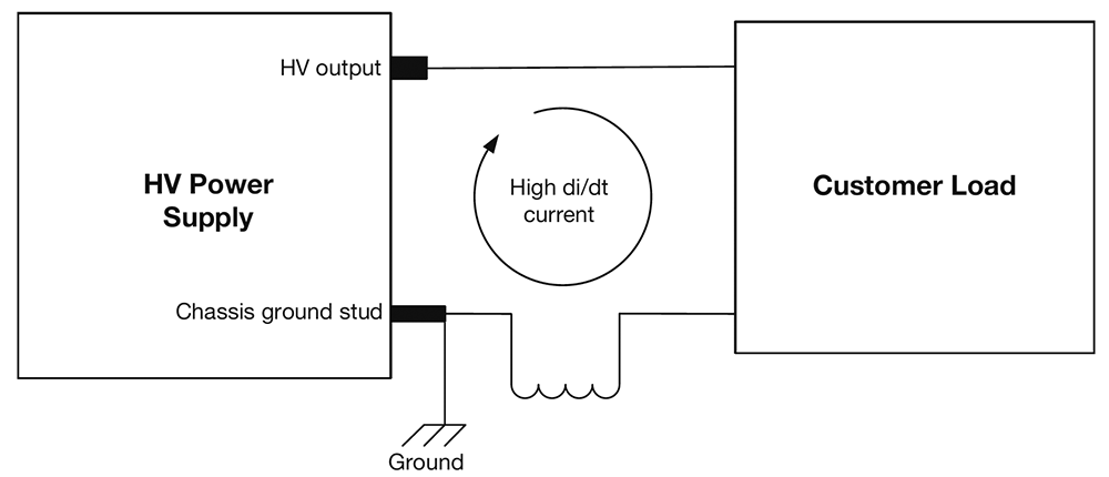 Figure 1. Improper grounding can lead to arc discharge.
Interface signals
These are the returns for any external signal interfaces such as programming, monitoring, enabling and interlock. The returns of all these signals should be connected to the common of the power supply and not directly to ground. The common inside the supply is connected to ground at the proper point to ensure that no transient voltages or RFI appear on the signal interface.
Multiple common connections are provided on the signal interface connectors of the power supply for this purpose. If the external interface cabling employs shielded or coaxial wires, then the shield of the wires must be separate from the common return and should be connected only at the power supply end to ground. A ground pin is provided on the interface connectors.
Load return
The HV load return, besides carrying load return current, also carries high peak discharge currents caused by arc discharges within the application’s load. When a HV power supply is quickly discharged, the stored energy inside the power supply is discharged through an internal limiting resistance. Since this resistance cannot be very high without degrading specifications or dissipating excessive power and heat, the peak currents are typically high, although of short duration.
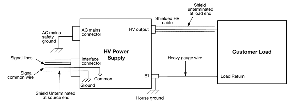 Figure 2. Recommended grounding arrangement.
This peak current flows through the load return wiring back to the energy source in the supply. Since these are fast rise-time transient currents, they can produce a significant voltage drop across the return wire if it is not carefully designed and returned properly. A large ground stud (designated E1 in Figure 2) is provided on all XP Glassman supplies for load return connections.
Figure 1 shows the situation that occurs when an arc discharge occurs. The high di/dt transient current flows through the return circuit stray inductances and even a very small wiring inductance can produce significant voltage spikes. In order to minimise these transient spike voltages:
• The load return should be a heavy wire connection or braid directly connected to the ground stud on the power supply chassis. It should be as short as possible and never coiled up. The load return should not be tied to house ground or any other ground return at the load end.
• A heavy wire connection should be made directly between the chassis ground stud and house ground. The AC mains ground should never be relied on as the only chassis-to-house ground connection and should never be a part of the grounding scheme. Mounting the load and the supply on a heavy ground plane is the best configuration but this is often not practical.
• House ground is typically the building frame, electrical conduits or water pipes.
Grounding guidelines
Figure 2 shows the recommended grounding arrangement. The signal interface wiring should be shielded if possible, with the shields connected to the power supply ground at the signal connector. A chassis ground pin is provided on the signal interface ‘D’ connector for this purpose. The signal interface returns should be connected to the common return pins on the interface ‘D’ connector and not the chassis or house ground.
The shield of the HV cable should not be terminated at the load end but should be cut off and covered. The recommended wire gauge for the load return wire is a function of the type of load but should generally be heavier than #6 AWG. Finally, the interface signal commons should be isolated from ground.
| Tel: | +27 11 454 8053 |
| Email: | [email protected] |
| www: | www.vepac.co.za |
| Articles: | More information and articles about Vepac Electronics |


© Technews Publishing (Pty) Ltd | All Rights Reserved
 printer friendly version