Test & Measurement


Debugging smartcards using a logic analyser

12 June 2013 Test & Measurement

Figure 1. An assortment of smartcards.

A smartcard, chip card, or integrated circuit card (ICC), is any pocket-sized card with embedded integrated circuits which can process data.

This implies that it can receive input which is processed – by way of the ICC applications – and delivered as an output.

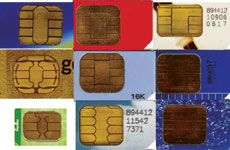
There are two broad categories of ICCs: memory cards contain only non-volatile memory storage components and perhaps some specific security logic, while microprocessor cards contain volatile memory and microprocessor components. The card is made of plastic, generally PVC, but sometimes ABS. It may embed a hologram to avoid counterfeiting.

Figure 2. Connections to a smartcard reader.

Using smartcards is also a form of strong security authentication for single sign-on within large companies and organisations.

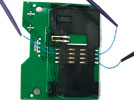
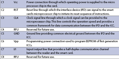
Table 1 describes the contacts of a smartcard and Figure 2 shows a typical smartcard reader which is sold on the market.

Table 1. Smartcard connections.

Measurement of ISO 7816 signals with a logic analyser

Figure 3. Protocol interpreter interface for smartcard ISO 7816 protocol.

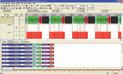
There are eight contacts on the smartcard in total. It is necessary to connect only three of them (clock, ground and I/O) to the Zeroplus logic analyser when measuring. All Zeroplus logic analysers come with 30 to 60 free protocol interpreters; one of these is the ISO 7816 protocol for communicating with smartcards. The captured waveform on a Zeroplus LA is displayed in Figure 3.

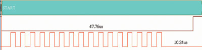
The signal structure of ISO 7816 is similar to that of RS-232C, the difference being that ISO 7816 relies on the clock to synchronise the data while RS-232C uses the baud rate of its signal to synchronise the data. ISO 7816 takes the 16 bits of clock as one unit to start sampling data – see Figure 4.

Figure 4. Analysis of the clock start bit and preamble.

As shown in Figure 5, after the clock signal after the start bit has generated 16 cycles (1 ETU), it is time to look for the data; the data packet is analysed in the same way.

Figure 5. Analysis of the whole ISO 7816 packet.

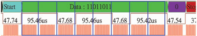
The format of the signal packet consists of the Start (1 bit), Data (8 bits), Parity Check (1 bit) and Stop (2 bits). Each bit on the data line needs to appear for 16 clock cycles (1 ETU) on the clock line, and the transmission direction of the data is fixed, which is LSB to MSB.

Setting up any protocol interpreters for the Zeroplus LA is made very simple by an intuitive user interface and context-specific menus. Only four properties in two categories need to be specified:

Pin assignment: Setting channel DATA and CLK;

Protocol analyser property: Set the periods of the clock as 1 bit in the ISO 7816 signal. The default is 16 periods, and the maximum can be set as 2048 periods.

Figure 6: Setting up the protocol analyser for ISO 7816 UART in the Zeroplus logic analyser software interface.

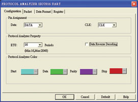
Figure 6 displays a screenshot of how to configure the interpreter for the ISO 1786 protocol.

Conclusion

The bottom line for the engineer or the manager is that using a logic analyser with a built-in protocol interpreter for the specific serial bus they are working on, like the Zeroplus logic analysers, will save a lot of time, very quickly paying for the cost of the analyser.

Gone are the days when an engineer can afford to sit for hours decoding digital busses on an oscilloscope. That is simply unproductive when there are logic analysers that can do that job in seconds and are affordable for the individual and small company. It simply does not make financial sense to debug today’s complex serial busses using yesterday’s methods.

As with all our other products at K Measure, we tell our new customers to bring it back for a guaranteed, no-questions-asked refund if the tool they buy does not save them time or cannot do what they expected. We have not had a single customer using that privilege in the full five years we have been selling Zeroplus’ logic analysers.

For more information contact K Measure, +27 (0)87 230 0134, [email protected], www.kmeasure.co.za


Credit(s)


Share this article:
Share via emailShare via LinkedInPrint this page

Further reading:

B&K Precision’s Series 1820B frequency counter
Comtest Test & Measurement
These compact and versatile instruments are designed for a wide range of frequency measurement applications, from telecommunications to verification and validation of oscillators.

Read more...
How transition-edge sensors detect microwave radiation
Test & Measurement
The elegant interplay of superconductivity, thermal physics, and precision electronics makes TES technology a cornerstone of modern low-energy photon detection.

Read more...
Compact high precision magnetometer
Future Electronics Test & Measurement
Bosch Sensortec has introduced the BMM350, a compact 16-bit, 3-axis magnetometer engineered to deliver high accuracy, low noise, and exceptional energy efficiency in space constrained designs.

Read more...
Ultra compact NTC thermistors
RS South Africa Test & Measurement
Murata Manufacturing Co. has expanded its compact NCU03 series of NTC thermistors with two ultra-small 0603M devices tailored for consumer and automotive designs.

Read more...
Omniflex uses LoRaWAN to track water usage
Omniflex Remote Monitoring Specialists Test & Measurement
Omniflex has helped New South Wales Ports improve its ability to track water usage by installing remote monitoring to 38 water meters at its Port Kembla site, sending the data to the NSWPorts web portal.

Read more...
Surviving the extremes: Understanding shock and vibration in MEMS sensors
Altron Arrow Editor's Choice Test & Measurement
By considering factors such as mechanical headroom, damping, and system-level robustness, designers can ensure that the chosen sensor not only survives, but performs reliably over time.

Read more...
Advanced pressure monitoring sensor
EBV Electrolink Test & Measurement
The Infineon KP497 is an advanced, highly integrated digital pressure sensor designed for demanding automotive and industrial applications, with a particular focus on battery management systems.

Read more...
Slimline 150 W bench PSU
Vepac Electronics Test & Measurement
The PeakTech P 6222 is the company’s new, slim laboratory power supply that offers precisely adjustable output values of 30 V and 5 A with a continuous power output of 150W.

Read more...
Redefining edge intelligence in RF analysis
Vepac Electronics Test & Measurement
The HAROGIC PXR Series bridges the gap between benchtop-grade RF performance and high-performance edge computing.

Read more...
Otto Wireless appointed as sole agent for Dragino Technology
Otto Wireless Solutions Test & Measurement
Dragino is a globally recognised leader in LoRaWAN and Internet of Things products and solutions, and is known for delivering reliable, cost-effective hardware.

Read more...


While every effort has been made to ensure the accuracy of the information contained herein, the publisher and its agents cannot be held responsible for any errors contained, or any loss incurred as a result. Articles published do not necessarily reflect the views of the publishers. The editor reserves the right to alter or cut copy. Articles submitted are deemed to have been cleared for publication. Advertisements and company contact details are published as provided by the advertiser. Technews Publishing (Pty) Ltd cannot be held responsible for the accuracy or veracity of supplied material.


© Technews Publishing (Pty) Ltd | All Rights Reserved