

Power Electronics / Power Management


Thermal evaluation of Infineon’s half-bridge EiceDRIVER ICs

13 November 2013 Power Electronics / Power Management

Only a few half bridge driver ICs currently available offer an integrated bootstrap function for the high-side supply. More typically the integrated bootstrap functions are realised by high-voltage FET structures, which are very area consumptive.

This is shown on the left in Figure 1. The resulting on-state resistance of the FET is above 120 Ω and therefore quite high. On the other hand, the high on-state resistance causes a high voltage drop at low duty cycles and additionally high power dissipation in the IC.
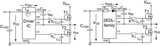
Figure 1. Bootstrap circuit of a half bridge configuration.<br>
Left: bootstrapping of competitor parts by FET.<br>
Right: bootstrapping of 2EDL family by bootstrap diode.
Figure 1. Bootstrap circuit of a half bridge configuration.
Left: bootstrapping of competitor parts by FET.
Right: bootstrapping of 2EDL family by bootstrap diode.

However, the advantages of a powerful integrated bootstrap function are striking. Firstly, the layout gets simpler because of fewer components on the board. Secondly, fewer components of course need less PCB space. The bootstrapping components and tracks are high-voltage ones and a suitable creepage distance must be considered when routing these connections.

Finally, better placement of the driver IC is possible in terms of the distance to the gate terminal of the power transistor. This also keeps the switching EMI low and optimises the switching performance, hence the switching losses of the power transistor.

In consideration of these advantages, Infineon developed its new half-bridge EiceDRIVER IC family, which uses integrated diode structures to overcome the disadvantage of a high on-state resistance bootstrap FET. This article presents evaluation results as well as a thermal model which is derived out of the measurements.

Thermal behaviour in application

Test setup

The application self-heating behaviour combines the static and dynamic losses of the driver IC. These are:

* Gate charge Qg of the driven power transistor including external gate-emitter capacitance CG according to Figure 1.

* Junction capacitance between high side and low side (CHL).

* Reverse recovery losses of the bootstrap diode (Erec).

* Resistive losses of the current limiting resistor (PRLim).

* Quiescent losses of the IC caused by the supply.

The test setup is defined on the right side of Figure 1. An infrared camera continuously measures the surface temperature of the device under test and communicates with a PC. The evaluation of the thermal performance of the 2EDL EiceDRIVER Compact family was performed using a 2EDL05I06PF device. The values of the test circuit are given in Table 1.
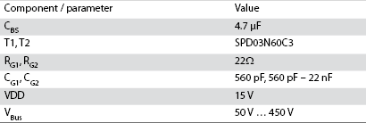
Table 1: Test circuit values.

The external gate source capacitors are chosen in order to obtain an approximate total gate capacitance of 1 nF. Two measurements with 10 kHz and 200 kHz were performed in order to evaluate the self-heating effect as a function of the DC link voltage VBus.

Additionally, it is proven by measurement that the device temperature scales linearly with the switching frequency. A third measurement shows the IC temperature depending on the external gate-source capacitance.

Influence of switching frequency fP

The blue curve in Figure 2 shows the absolute temperature TIC of the device surface, while the red curve shows the relative temperature increase ΔTIC above ambient temperature. The lines are strictly linear, which proves the linear dependency of the power dissipation on the switching frequency. It gives a simplification for the thermal modelling further below.
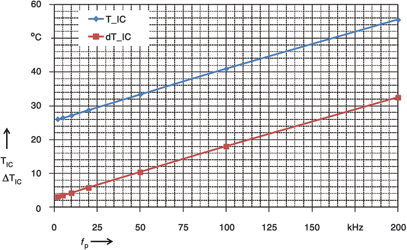
Figure 2. IC surface temperature of EiceDRIVER Compact 2EDL05I06PF as a function of switching frequency (V<sub>Bus</sub> = 300 V).
Figure 2. IC surface temperature of EiceDRIVER Compact 2EDL05I06PF as a function of switching frequency (VBus = 300 V).

The temperature increase of the EiceDRIVER IC operating at 200 kHz is excellent at around 31°C. This measurement shows that the IC is capable of supporting modern switch mode power supply technologies.

Influence of DC bus voltage

Figure 3 shows the relative temperature increase relative to DC link voltage variation of the IC at two different switching frequencies. The linear approximations are given by these equations:
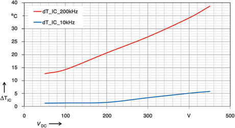
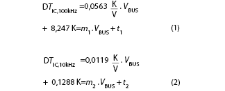
Figure 3. IC surface temperature of 2EDL05I06PF as a function of the dc link voltage.<br>
Blue: switching frequency V<sub>Bus</sub> = 10 kHz.<br>
Red: switching frequency V<sub>Bus</sub> = 200 kHz.				`
Figure 3. IC surface temperature of 2EDL05I06PF as a function of the dc link voltage.
Blue: switching frequency VBus = 10 kHz.
Red: switching frequency VBus = 200 kHz. `

The total influence of switching frequency and the bus voltage can be extracted by deriving a linear function for m = m(fP) and t = t(fP) by using m1, t1, m2 and t2:

Combining equations 1 – 4 results then in the final thermal model depending on the bus voltage VBus and the switching frequency fP:
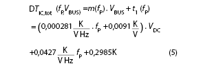
where the switching frequency fP is given in kHz.

Influence of gate capacitance Cgs.

A third measurement evaluates the dependence of the IC temperature on the gate load. This was achieved by adding higher values for the external gate-source capacitance Cgs. The switching frequency was set to 100 kHz and the bus voltage to 300 V. The IC temperature can be approximated as a linear function of the gate load, as shown in Figure 4.
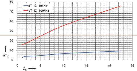
Figure 4. IC surface temperature of 2EDL05I06PF as a function of the gate load 
(V<sub>Bus</sub> = 300 V, f<sub>P</sub> = 100 kHz).
Figure 4. IC surface temperature of 2EDL05I06PF as a function of the gate load (VBus = 300 V, fP = 100 kHz).

For more information contact Davis Moodley, Infineon Technologies, +27 (0)11 706 6099, www.infineon.com


Credit(s)


Share this article:
Share via emailShare via LinkedInPrint this page

Further reading:

Surface mount power amplifier for high-power applications
RF Design Power Electronics / Power Management
The GNA-63-5W+, from Mini-Circuits, is a GaN MMIC Power Amplifier (PA) designed for demanding RF applications requiring high efficiency, excellent linearity, and a compact footprint.

Read more...
1200 V QSiC modules
Power Electronics / Power Management
SemiQ Inc has launched the QSiC Dual3, a family of 1200 V half-bridge MOSFET modules for motor drives in data centre cooling systems, grid converters in energy storage systems, and industrial drivers.

Read more...
MCOTS transient filter for military applications
RFiber Solutions Power Electronics / Power Management
SynQor has announced the new MCOTS-F-28-T-HE transient half-brick filter, the latest addition to its MCOTS product family.

Read more...
Expanded range of high-thermal-performance QSiC modules
Power Electronics / Power Management
SemiQ’s half-bridge series for data centre power converters and industrial motor drives features low RDSON SiC MOSFETs and parallel SBD diodes for best-in-class power density and conversion efficiency.

Read more...
Transporting lithium batteries and IoT devices
Power Electronics / Power Management
With billions of rechargeable and non-rechargeable lithium cells and batteries powering most of the world’s consumer and industrial electronic devices, shipping them to customers through vast global logistics chains is often an overlooked topic.

Read more...
Setting a new benchmark for high-power DC load testing
Conical Technologies Test & Measurement Power Electronics / Power Management
The new ITECH IT8900G/L high-speed, high-power DC electronic load offers a powerful combination of speed, scalability, precision and high-power density.

Read more...
Quality batteries are critical for IIoT
Uniross Batteries Power Electronics / Power Management
Batteries intended for use in industrial operations must indeed offer complete reliability under extreme environmental conditions, resistance to vibration and harsh environments.

Read more...
12 kW hybrid inverter
Power Electronics / Power Management
Sungrow recently unveiled its next-generation residential energy storage solution, expanding its power range from 5 kW to 12 kW with the introduction of the new MG12RL hybrid inverter.

Read more...
40 W and 75 W railway DC/DC converter
Brabek Power Electronics / Power Management
RECOM has announced two new cost-efficient DC/DC converters for the rail market with an ultra-wide 11:1 input range to cover all nominal input voltages from 24 to 110 V DC.

Read more...
Power modules for solid-state transformers
RS South Africa Power Electronics / Power Management
Microchip’s new 3,3 kV silicon carbide modules deliver the required thermal performance and efficiency for SSTs to increase power available for token generation.

Read more...


While every effort has been made to ensure the accuracy of the information contained herein, the publisher and its agents cannot be held responsible for any errors contained, or any loss incurred as a result. Articles published do not necessarily reflect the views of the publishers. The editor reserves the right to alter or cut copy. Articles submitted are deemed to have been cleared for publication. Advertisements and company contact details are published as provided by the advertiser. Technews Publishing (Pty) Ltd cannot be held responsible for the accuracy or veracity of supplied material.


© Technews Publishing (Pty) Ltd | All Rights Reserved