


Spring contact probes are used as the interconnection medium between the unit under test (UUT) and the tester. This article gives a general discussion of probe fixturing, limited to the most common types of test fixturing.
Loaded board and functional test
The test fixture environments that use spring probes can be grouped into two categories, loaded board test and functional test. Loaded board test can be defined as either the task of measuring all or key components that have been installed on a PCB to determine whether they are the correct components and/or within specified parameters or tolerances for that particular device. This type of test is commonly referred to as in-circuit test (ICT).
The second category of loaded board test may involve simple open and shorts tests on the board to verify manufacturability standards. During this second test, the spring probes are contacting test points and the tester is performing an MDA test or manufacturing defects analysis. Simply put, it is looking for production deficiencies, such as device leads not soldered, cold solder joints, bent connector leads that have not completely installed into plated through holes, or solder defects such as solder bridges between two traces.
Both of these types of loaded board tests are supported by large and small companies, which produce automated test equipment (ATE) to perform these functions in extremely short periods of time, very often in seconds.
Functional test, where power is applied to the loaded board to determine whether the circuit will perform the functions as they were designed, usually involves custom built test equipment and custom test fixturing. It uses cabled connectors in conjunction with test probes to apply power and ground. The probes also make the connections to specific areas of the board during test. Functional test takes a significantly longer time to perform than in-circuit test, since the board components are actually being exercised during the test.
Most test fixtures have some commonality in the components that make up the physical fixture:
* Probe plate for mounting the probes and receptacles;
* Top or diaphragm plate to support the UUT;
* Tooling for registering the UUT to the probe pattern;
* Wiring to connect the probes to the tester;
* Source of mechanical force to drive the UUT down onto the probe pattern, which is largely dependent upon the test equipment being used.
Probe plate
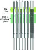
Most commonly, the test fixtures use spring contact probes combined with a receptacle. The receptacle is designed to press-fit into a drilled hole in the probe plate and will serve as the attachment for the connecting wire (see Figure 1).
The probe plate must be made of a material which is suitable for precision drilling and rigid enough to support the combined force of the probes without flexing. The most common probe plate material is Garolite, also know as G-10 or FR-4 in its fire-retardant grade. G-10 is a glass epoxy laminated material that allows for precise machining, exhibits a very stable thermal coefficient of expansion (TCE), and is extremely rigid.
Other available materials include composites and laminates such as Phenolic and Bakelite, but they are more difficult to machine. Lexan and various acrylics are commonly used materials, but lack the strength and rigidity of G-10 and fracture easily when stressed. Delrin and other thermoplastics should be avoided. They are thermally unstable and do not provide the superior anchoring characteristics of G-10 when press-fitting the receptacle into the drilled hole.
The probe plate should be thin enough to drill an accurate hole, yet thick enough to provide adequate rigidity and sufficient guidance for the receptacle. For longer probes, with 6,35 mm travel, a thickness of 9,53 to 12,70 mm is recommended. Although as UUTs become densely populated with semiconductor devices and test point counts increase, thicker probe plates are being used. For shorter probes, with 1,27 to 2,54 mm travel, a thickness of 6,35 mm is adequate (see Figure 2).
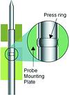
The IDI receptacle is designed to press-fit into the probe plate. This is done by drilling a hole oversize for the receptacle diameter, yet undersize for the press ring. A recommended hole diameter is listed with each receptacle on its catalogue page. The receptacle is dropped into the mounting hole; if the recommended hole size is used, it will slide down until the press ring contacts the upper surface of the probe plate. An insertion tool should then be used in combination with a 'soft' mallet, either nylon, rolled leather or paper, to drive the receptacle into the hole using several taps to completely set the receptacle to the prescribed height. Insertion tools are available from IDI, which leave the top of the receptacle at a fixed distance from the surface of the probe plate. Use of a metal headed hammer can cause damage to the receptacle.
Once the receptacles have been installed, wiring is then required. Receptacles are available in various forms to meet all wiring needs:
* Solder cups terminate the wire using solder. Larger gauge and multi-strand wire should be terminated using this technique.
* Crimp terminations are also available for larger gauge wire and/or stranded wire. IDI offers crimping tools designed specifically for our receptacles.
* Wire wrapping, by far the most common wiring technique, involves twisting a single strand wire around a square wire post. The most common post diameter is 0,635 mm square and will accommodate wire gages from 30 to 26 AWG while allowing for multiple wraps per pin.
The wiring is the media between the probe receptacles to the fixture interface. The fixture interface may be discrete connectors, which will be connected via cable; interface boards; interface blocks; or individual interface pins to connect to the tester.
The tester platform dictates the interface method that is required. Probes can then be inserted into the receptacles to populate the fixture. The probes should be inserted using a piece of plastic pressing on the probe tips. Use of a metal tool may damage delicate style tips. Care should be taken not to apply more force than is necessary to completely seat the probe.
Top or diaphragm plate
The manner of UUT guidance and tooling is dependent on the type of test performed. Loaded circuit board assemblies may be mounted above the probes on a top or diaphragm plate. This plate is drilled to match the probe array on the probe plate. The drilled holes in the top plate help to guide the probes to the test targets on the board. In this instance, it is critical that tooling pins pass from the probe plate, where the receptacles are resident, through the top plate to tooling holes on the UUT, so that the UUT is accurately registered to the probe array on the probe plate. The UUT may also be aligned with clips but final alignment should always depend on the insertion of a registering tooling pin into a precise datum hole on the PCB.
Fixture actuation
The final consideration is the application of force to drive the UUT down onto the probes. This is largely dependent upon the design of the tester, which may make provision for the type of force. Many loaded board testers will use either pneumatics to force the UUT down or vacuum to draw the UUT down to the probes. The ATE platforms that are most commonly used in medium to high volume production environments will use vacuum, mechanical, or pneumatic clamps to secure the test fixture to the tester and system vacuum to draw the UUT down for the test cycle.
The use of vacuum to draw the UUT down dictates that the fixture has a sealing gasket on the top plate that follows the outline of the UUT and requires that it has no open vias or holes that inhibit the evacuation of air. When applications do arise with open vias or components missing during test, adapting a vacuum box to the top plate allows for the vacuum method to be used. The vacuum box covers the board and holds it in place when the probes make contact with the UUT while the system's vacuum holds the cover in place.
Also common, pneumatic test fixtures mechanically move the board and top plate down onto the probe array or a platen plate using nylon pressure fingers that are designed into some MDA type testers. The pressure fingers push down on the UUT itself to make contact with the test probes. Pneumatic fixtures are largely used when extremely accurate registration is required, since pneumatic cylinders are more controllable and some boards are prone to flex during the vacuum phase of fixture actuation. Use of pneumatic pressure is also common when staged actuation is required, such as dual level testing, or probe movement other than vertical as in a side access mechanism where a board mounted connector is being probed horizontally.
Mechanical fixtures, which use human intervention, are also common when the test equipment is custom. These mechanical fixture kits are available from many vendors and provide labour saving mechanisms, such as over-clamp gates with cam mechanisms to minimise the work needed to force the UUT down onto the probe array. These fixture kits and gates do not usually accommodate a large number of test points or probes due to the amount of spring force that must be overcome.
Whether it is an in-circuit or functional test; vacuum, pneumatic, or mechanically actuated, spring contact probes are the heart of board test. IDI makes the connection possible.
For more information contact Colin Pepin, Connecta, 011 463 2240.


© Technews Publishing (Pty) Ltd | All Rights Reserved
 printer friendly version