


Ref: z2615192m
The CC1000 RF transceiver from Chipcon is ideally suited for use in the fast-growing wireless game controller market. The CC1000 is a true single-chip UHF transceiver developed for very low power consumption and low voltage operation. Based on a 0,35 µm CMOS technology this is the only product currently available that offers a unique combination of low cost, high integration, high performance and flexibility, thus setting a new standard for shortrange wireless communication devices.
Abstract
Wireless game controllers are rapidly gaining market acceptance. Chipcon's CC1000 RF Transceiver is ideally suited for this type of application, offering a unique combination of time and cost-effective design features including high data rate, low power consumption, low cost, integrated bit decision and synchronisation, frequency agility and flexibility.
After a brief review of the CC1000's technical details, requirements and benefits, examples of two application approaches for supporting multiple players are presented. One approach is based on the frequency-division multiplexing (FDM) concept, the other on the time-division multiplexing (TDM) concept. Implementing one of these approaches makes it possible to design a system specifically for the available frequency ranges: 433 MHz and 869 MHz in Europe, 902-928 MHz in the USA.
The system suggestions assume the controllers are sold in units with one controller and one receiver, where the receiver is plugged into the controller port of the game system. Customer feedback and surveys indicate this is what most manufacturers and end-users want. Channel allocation can be done manually by means of a switch, or automatically via an arbitration protocol.
Introduction
Console and computer-based gaming is bigger than ever, targeting larger and broader age and demographic groups. The gaming systems are developing so rapidly that each new generation increases the processing power and memory bandwidth tenfold. The game controllers are also developing accordingly, progressing from first-generation devices using simple joysticks and paddles to controller pads, and then on to specialised controllers such as steering wheels and flight yokes. Today's controllers, both analog as well as digital, integrate control sticks, game pads buttons and even 'force feedback' and vibration to give the players an even greater sense of interactivity and reality. As sophisticated as these controllers may be, they all have a fundamental, significant limitation - the players are, literary, tethered to the game system.
As early as the early 1980s, Atari explored the concept of wireless controllers for its 2600 (VCS) game system, but players have only recently shown a real interest in wireless devices. Among other factors inhibiting their acceptance, the early units were bulky, unreliable and expensive. Now, however, all these technical hurdles have been overcome, and it is possible to produce exceptionally light, inexpensive and reliable units.
Requirements
The prime purpose of a handheld game controller is to transform the input commands a player issues by manipulating the buttons, joystick, pad, etc on the controller into electrical signals, which are then sent to the game system 'base unit' for processing.
The response time must be virtually immediate; so short that any lag between the time a player issues a command and the reaction is seen on-screen is imperceptible. To sustain the fun and interest the system must be reliable.
In addition, a wireless controller should not be much larger, heavier or more expensive than a wired unit. Since 'wireless' implies that the controller must run on battery power, battery life must be long enough so that play is not constantly interrupted to change or recharge batteries. Infrared technology, used in many TV, VCR and stereo remote controllers, has been applied in some game controllers, but the fact that the infrared beam must be aimed directly at the receiver is a major drawback of this technology. One of the main benefits of a wireless controller is the freedom of movement it gives the players.
Players appreciate - and want - a chance to move around while playing without being entangled in a mass of cables.
Supporting multiple players
Most game systems enable up to four players to play simultaneously and an effective RF solution must support this many players. Since RF is a shared medium, this means an effective implementation must allow four simultaneous links. This can be done by frequency division multiplexing (FDM) and/or by time-division multiplexing (TDM).
RF systems are based on modulating the data to be transmitted (known as the baseband signal) onto a high-frequency RF carrier signal. FDM is implemented by modulating the various data streams onto carriers with different frequencies. As long as the carrier frequencies are far enough apart, the data streams will not interfere with each other.
In contrast, the principle of TDM is based on sharing a single carrier, with the different data streams being interleaved in time. The available time is divided into time slots, with each data stream using a different slot.
These two principles can also be combined so that multiple carriers are used, each with its own time-slot allocations. Two practical implementations, one using FDM and one using TDM, are presented later in this article.
When several transceivers are operating in close proximity to each other, it is important to have good blocking and saturation characteristics. Blocking is a measure of how strong an interfering signal (typically called a 'jamming signal', the terminology originates in military applications) can be before the range of the system is reduced. This is especially important when using FDM, where a unit receiving a signal on one frequency does not want to be disturbed by another unit operating on another frequency. It is also important to prevent disturbance from other systems. Saturation is a measure of the signal strength a receiver can tolerate and still receive the data correctly. If this figure is too low, the radio link will have a minimum usable range as well as a maximum range.
Frequency allocations and regulations
Although radio regulations are, unfortunately, not standardised worldwide, the number of different regulations with which a developer must comply is limited.
The United States, Canada, Australia and several other countries have regulations based upon standards set by the Federal Communications Commission (FCC, www.fcc.gov) in the US. For wireless game controllers, the applicable frequency band is located between 902 MHz and 928 MHz. This is a wide band, where four separate frequency channels can be easily accommodated.
Most European countries abide by regulations defined by the European Telecommunications Standards Institute (ETSI, www.etsi.com). Recommendations are also given by the European Conference of Postal and Telecommunications Administrations (CEPT, www.ero.dk). In Europe, there are two frequency ranges applicable to wireless game controllers: 433,050 MHz to 434,790 MHz (power density limited to -13 dBm/10 kHz) and 869 700 MHz to 870 000 MHz.
Bluetooth and wireless LAN systems use a globally harmonised RF band, 2,4GHz, but as these systems become more widespread this band will, accordingly, become more congested. Microwave ovens also emit radiation in this frequency range. Interference from this addition to modern kitchens should not be underestimated. RF transceivers operating at this high frequency consume more power, are more expensive than transceivers operating at lower frequencies, and have a higher propagation loss that, in turn, requires more power to reach the same range. The power requirements of 2,4 GHz transceivers are typically several times higher than devices operating below 1 GHz.
Higher-frequency systems are also harder to implement, requiring special PCB materials and exotic components. For ISM-band devices operating at frequencies below 1 GHz, standard FR-4 board material and standard surface-mounted passive components is sufficient.
Data-rate requirements
The amount of data generated by a modern game controller is assumed to be on the order of 2 to 10 bytes. The digital Play Station pad sends 2 bytes of data payload, for example, while the analog DualShock pad sends 6 bytes. Analog values are typically converted into digital values with 8 bits of resolution. For a typical game pad with two 8-bit analog sticks and 16 digital buttons, the data total is 6 bytes (48 bits) if the total state of the controller is to be transmitted. For a player to feel that controller movement is smooth, the data should be refreshed 100 times each second or more. Hence, the raw data-rate required is 4,8 kbit/s. However, transmission of an RF data packet requires overhead. At the start of each message, a preamble of alternating ones (1) and zeros (0) are required for the receiver to synchronise. An ID tag should also be included so that the game system knows which controller is sending a message, as well as a checksum to verify that the data is correct.
To use TDM, the channel data-rate is divided among the different data streams. This means that if a game has four players, the channel data-rate must be four times the desired data-rate for each player.
Most RF transceivers are half-duplex devices; the devices can either transmit or receive, but cannot do both at the same time. The RF link between the controller and the game system is one- or two-way depending on whether or not data is transmitted back to the controller. A two-way link is needed if the controller includes options such as a LCD screen, force feedback, vibration mechanism, etc.
If a two-way link is used, a time-division duplex scheme will allow data transfer in both directions; when data is not flowing from the controller to the game system, it is flowing from the game system to the controller.
RF transceiver
A wireless game controller requires an RF transceiver that has a high data rate (for ISM-band devices, data rates between some hundred bits per second up to around 100 kbps are usual), low current consumption, fast RX-TX switching, integrated bit synchronisation and support for multifrequency operation. The CC1000 from Chipcon meets all these requirements.
The CC1000 supports data rates up to 76,8 kbps, allowing even complex controllers to transmit data with low latency.
The CC1000 has a voltage supply range of 2,1 V to 3,6 V, allowing it to run on two standard AA or AAA batteries. The low current consumption of less than 10 mA at 868 MHz and 915 MHz (the current consumption at 433 MHz is even lower) enables a play time of more than 200 hours (using alkaline AA cells with a capacity of 2600 mAh and allowing for current consumption by the micro controller). In power-down mode, the CC1000 draws less than 1 µA. Ultimately, this means the standby time for the controller is only limited by the shelf life of the batteries.
The CC1000 can switch between RX and TX or between two different frequencies in 250 µs or less, ensuring as little overhead as possible in a two-way application. Multifrequency capabilities are a must for implementing FDM multiplayer solutions. The frequency synthesiser of the CC1000 can be programmed in steps of 250 Hz for any frequency between 300 MHz and 1 GHz. Another notable feature of the CC1000 is that it can handle all the relevant frequency bands in Europe and the US. In fact, the CC1000 can operate in the 869 MHz band and in the 902-928 MHz band using the same external components. Thus, a controller can be used both in Europe and in the US simply by letting the microcontroller program different frequency settings into the transceiver.
The CC1000 also has integrated data decision and synchronisation, requiring little processing overhead from the attached microcontroller. To top this off, the CC1000 requires very few external components, keeping cost, physical size and complexity down.
The blocking characteristics (+40 dBc at ±1 MHz) of the CC1000 are very good. This means that a jamming signal 1 MHz away from the carrier frequency can be 40 dB stronger than the wanted signal before reception is impaired. The saturation spec is +10 dBm, meaning that an RF link using the CC1000 does not have a minimum range unless an external PA or high-gain antenna is used.
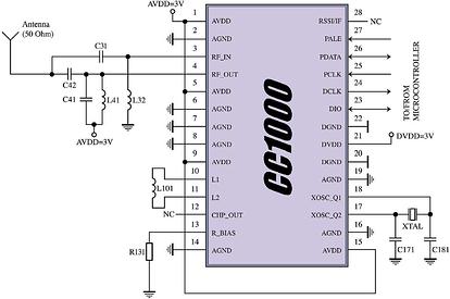
The CC1000 is easily interfaced to a single-ended 50 Ω PCB antenna; no balun or tricky tuning is required. The CC1000 can also share the reference crystal with a microcontroller, lowering the total number of parts.
Implementation
A practical implementation of a wireless game controller will look something like the block diagram below:
In the controller unit, the microcontroller continually samples the attached controls (potentiometers, buttons, etc). Digital controls are read directly, analog controls are run through an A/D converter and sampled. The microcontroller assembles a data packet, and sends it to the receiver unit that is connected to a PC or game console via the standard controller port. A microcontroller in the receiver unit decodes the data packet and sends the appropriate data to the PC or console. If the system is to be two-way, the receiver unit will also transmit data back to the controller in the same way.
For marketing considerations, one controller unit and one receiver unit are sold as a game 'package'. A purchaser wanting to include more than one player must buy several sets. This packaging model is generally well-accepted by customers and is a benefit to the retailers that would otherwise have to stock several different units if a combined receiver unit for several players were sold separately from the controller units. Wired controllers are also sold singly.
FDM or TDM?
Whether an implementation is based on FDM or TDM depends on the frequency targeted, the data-rate needed, the number of players supported and whether the link is to be two-way. As mentioned earlier, the approaches can also be combined in order to optimise frequency usage.
Also note that there are no differences in the hardware between the two; the difference is purely in how the microcontroller software is written.
Case 1: FDM-based system
A game system based on frequency-division multiplexing (FDM) is targeted at the 902 MHz to 928 MHz band in the US and can support four or more simultaneous players with 76,8 kbps available for each player. The same system can also operate in the European 433 MHz band, but because the available RF bandwidth is limited, a maximum of only three players can be supported.
If operation is one-way, Chipcon's CC1050 transmitter can be used in the controller units instead of the CC1000 transceiver. A pure transmitter is significantly lower in cost than a transceiver. The controller can transmit continuously since the data does not need to be sent in packets. This means that the entire 76,8 kbps bandwidth is available for controller information, with no other overhead. Hence, very high update rates can be supported. If the total data from the controller is less than 9 bytes (which would cover two 8-bit analog sticks, 24 digital buttons plus a 16-bit CRC), the update rate will be over 1000 times each second, providing the player with an extremely responsive controller. This approach is also the simplest with regard to protocol and software implementation. Even with continuous transmission, the battery life of a system using the CC1000 at low output power levels can be well over 200 hours using two alkaline AA batteries. When the controller has not been used for a time, it can go into standby mode, with a battery life only limited by the shelf-life of the battery.
In a two-way application, data will be transmitted alternating each way. For each data packet, a minimum of 16 bits of preamble is needed, in addition to a start-of-frame/ID word. Hence, the packet overhead will typically be 32 bits. The transceiver RX/TX switch time is 250 µs - around 20 bits with a 76,8 kbps data rate. The data rate (DR) available is given by:
For example, if the system switches 200 times per second (100 packets sent each way each second), the data rate available is 66,4 kbps. This data rate must be split between the data going each way; usually there will be less data sent from the game system to the controller unit than data sent from the controller to the game system.
Case 2: TDM-based system
A system based on time-division multiplexing (TDM) can be used in any frequency band, but is especially useful in the narrow European 869 MHz band. Players must share the channel data-rate between them. If two-way operation is desired, the data rate available for each player will be very low and this is not recommended if four players must be supported.
For a one-way solution, each player can be allocated a time slot. Each controller unit transmits in its time slot if it is active. All units (both controller units and receiver units) synchronise themselves on each start-of-frame word sent by all controllers. In this way, all units are properly synchronised in time. The receiver units are in receive mode all of the time, but ignore the data not intended for them. A controller unit transmits only in its own time slot and is in receiving mode the rest of the time. The overhead will be the same as for the two way FDM-based system - 32 bits of protocol overhead and 20 bits of RX/TX switching overhead (per player). In fact, the controller unit switching from RX to TX may start early, leaving the PA off until the start of its time slot. In this way, the RX/TX overhead can be eliminated.
If this optimisation is performed, the total data-rate budget using a single RF carrier frequency and four players becomes:
[76 800 - (4 x 100 x 32)]/4 = 16 000 bit/s, where 100 is the number of packets sent per second for each player.
In this case, each packet can have a data payload of 20 bytes.
Depending on the application, there is another way to improve the data rate of a TDM system. Most of the time, the number of wireless controls in use simultaneously will be fewer than four. The active controls can share the bandwidth between them. In fact, most often only one player will be active and in this case the active controller can use the entire 76,8 kbps data rate by itself.
Channel allocation
Regardless of whether data channels consist of time-divided time slots or frequency-divided RF channels, the available channels must be allocated to the controllers. This may be done manually by simply including a multiway switch on the units, or automatically by an arbitration protocol. The microcontrollers of the controller and receiver units can be programmed with unique IDs, so that the system knows which controller belongs to which receiver. During power-up, it is then easy for the controller and receiver to find each other - and frequencies can be allocated based on either controller port numbering or on a first-come, first-served basis.
The receiver unit
The receiver unit accepts the data from its associated controller unit, and converts it to a form specific to the game system. For instance, Play Station 2 has a polling system where the console requests information from the controllers. In this instance, the receiver unit would buffer the data received from the controller unit, and present the latest values when queried by the Play Station. A CRC checksum can be used to validate each packet. If there is an error, the data from the packet are discarded, and the values from the previous packet are used. This ensures that bit errors do not result in erroneous control input to the game system. The receiver could even interpolate between received values in the case of analog controls.
Conclusion
Wireless game controllers are a fast growing market. RF technology in general, and Chipcon CC1000 technology in particular, is very well-suited for these applications, offering an outstanding combination of low price, high data rate, multichannel operation, ease of use and flexibility.
For more information contact Components & System Design, Kevin Jurius, 011 979 4274, [email protected]


© Technews Publishing (Pty) Ltd | All Rights Reserved
 printer friendly version