


Although the effects of noise problems in digital and analog portions of circuitry can be very different, they do not necessarily need different solutions. Often the root cause is the same - the board layout has placed sensitive tracks or pins next to noisy tracks or pins. Clearly, the first thing to try is to physically separate the noisy traces from the high-impedance lines. If this is not possible, there is another way.
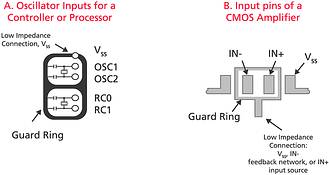
Let us consider a digital example - a PWM pulse interfering with a low-power oscillator circuit. Since the oscillator circuit is designed to draw very little power during operation, it has a very high internal impedance. As a result, the switching noise of the PWM pulse is capacitively-coupled from trace to trace into the oscillator circuit. This will cause clock jitter and, at worst, clock irregularity. If it is not possible to separate the traces sufficiently, the answer is to use a guard ring, as shown in Figure 1A.
The results of noise in an analog circuit can be equally destructive, even though the way in which the problem arises may be very different. A typical example would be a high-impedance pin of an operational amplifier located close to a track with a different voltage potential or, even worse, switching noise. It is very easy to overlook the first possibility.
For example, if the input pins of an operational amplifier have a very high impedance, the input bias current will be as low as a few picoamps at room temperature. The leakage current between the higher-potential track and the high-impedance one will make the input bias current of the amplifier appear to be higher than it really is. This leakage current could be a result of close traces and aggravated by humidity, board contamination or dust. The leakage current can be as much as five to 10 times higher than the input bias current, and can create severe problems. This is another example where the pins may need a guard ring as shown in Figure 1B.
A low-impedance guard ring, which separates sensitive operations from higher voltage or noisy events, is a very useful technique. Low impedance implies that it has low resistance as well as low inductance. In Figure 1A, the guard ring surrounds the processor or controller pins, oscillator clock and capacitors. Ground is connected to the guard ring to establish a low impedance potential. The guard ring in Figure 1B is connected to a low-impedance voltage that has a similar level to that on the input pins of the amplifier.
There are three common places to find these low impedance voltages. Ground is the most likely connection and this is the best solution if one of the amplifier inputs is connected to ground. Alternatively, the guard ring can be connected to the inverting input of the amplifier if the feedback impedance and source impedance to the amplifier are relatively low. A third option is to connect the guard ring to the non-inverting input of the amplifier, provided this pin is connected to a low impedance voltage source.
In both circuits described here, the underlying cause of the problem was an impedance mismatch. Once this is understood, the solutions, including guard rings, can be used to good effect.
For more information contact Avnet Kopp, 011 809 6100, Memec SA, 011 897 8600 or Tempe Technologies, 011 452 0530.
| Email: | [email protected] |
| www: | |
| Articles: | More information and articles about Tempe Technologies |


© Technews Publishing (Pty) Ltd | All Rights Reserved
 printer friendly version