


Today's FPGA designs are becoming larger and more complex, with hundreds of macros, intellectual properties, and re-usable parts of legacy designs. FPGA designers now face the huge challenge of rapidly describing the interfaces, ie, hierarchies and interconnections, for a new design using these parts.
Traditional approaches spend too much time drawing large block diagrams or writing thousands of lines of structural HDL. These traditional approaches also make it very difficult to visualise and document the design. Hence, ease-of-re-use and easy communications are becoming more and more important in HDL FPGA design.
Mentor Graphics' FPGA Advantage provides the interface-based design (IBD) paradigm, which is a new approach to design entry. It helps HDL designers in these tasks: quick design creation, simplified design re-use, visualised design documentation, and easy communication in the design intent. HDL structural code can be generated automatically from an IBD design.
The concepts
IBD: Interface-based design is a methodology that defines the structure of a design in terms of the interfaces between blocks and components.
IBD Editor: A design creation tool that describes a design using IBD methodology. The hierarchies and interconnections of a design are represented by one or more Interconnect Tables.
ICT: Interconnect Table, used in the IBD Editor, and describes the connections between one or more block and components using a table-based method.
IBD View: A design unit view created using the IBD Editor.
A simple IBD design created by FPGA Advantage is shown in Figure 1.
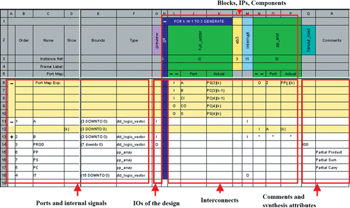
Typically, an IBD view contains the following parts:
* Ports/signals: Define the ports of the current design components to be connected, including names, types, bit widths and the declaration order of the ports/signals in the generated HDL.
* IO ports of the current design: Define the ports for the current design unit. I/O/B/U stands for Input, Output, Bi-directional and bUffer (VHDL only). This information can be extracted from its interface definition or up-level design automatically.
* Blocks, IPs and components: Design units instantiated in the current level.
* Interconnections: Interconnections between different units in the current design, using I/O/B/U in the corresponding cells to represent Input, Output, Bi-directional and bUffer. For components, port names and actual values connected to the port are shown in additional expandable rows.
* Comments and synthesis attributes: Define in-line comments or set synthesis attributes.
* Sub-tables: Can be used to describe a large circuit in partial views.
Design creation
In a large design with hundreds of instances, HDL designers spend a large amount of time connecting the instances together instead of real design definition. It is very easy to make a mistake while working on a huge textual file; wrong connections or undesired open ports lead to malfunction of the circuit and days of function debugging, thus delaying the product to the market.
With the IBD editor, a 20 x 20 table, for example, can represent a thousand lines of HDL code. You can easily create, view and find all ports, internal signals, instances and connections among them. The columns contain the blocks or components that will be connected while the rows of the table display the signals/ports that are available as connections to the blocks. The intersection of rows and columns indicate the connection points of signals to ports on the blocks, ie, signals that are either driving the blocks or signals being driven by the blocks. The corresponding structural HDL codes can be generated on-the-fly.
In addition, the IBD editor provides the following advanced features to help the creation:
* Complex connections: For example, using signal slice or Port Map Frame to make a partial connection, or to connect individual slices of a signal to separate ports on the component.
* The generation frames: Used to produce repeatable, conditional or alternative part of the circuits. They represent the HDL structures of For statements, If statements, and Block statements.
* Partial interconnect tables: To create/display the interconnection between any subset of selected instantiated views or signals in an IBD view. Partial tables break down a large design in smaller chunks for documentation and legacy design understanding.
* Add signal stubs/port Ios: A quick way to add net declarations corresponding to the unconnected ports on a selected component.
* Add a synthesis property: Add a generic or tool specific synthesis attribute to guide the synthesis process. The result will be included in the generated HDL, or a separate constraint file.
* Auto-text-completion: For speeding the entry phase of signal types, constraints, directions, and connections. For example, in the Type field, you can type i for integer.
* Show unconnected ports: To make sure that all ports of a selected unit are being connected.
* FPGA Vendor IP: IP cores from Altera's MegaWizard and Xilinx's CORE Generator can be easily dragged and dropped from FPGA Advantage's design manager into the IBD table editor for quick hook up.
Design re-use and visualisation
An IBD view gives a compact, simplified format to understand hierarchical and connection information of legacy designs and Intellectual Properties. With the built-in leading technology of HDL2Graphics, you can convert an existing textual design to this tabular format. The design can be easily understood, all the inputs and outputs, internal signals, connections are represented in one simple table for easy navigating and modification.
Design documentation
Instead of using pages of HDL code as part of your document, you can use one page of a table to make your document more efficient and understandable. The communication within your team and company is simplified and effective.
The IBD table can be inserted into your document by using the Microsoft OLE feature on Windows platform, or can be exported as standard HTML format on all supported platforms including UNIX and Linux. Other people can review your design without accessing your design database, or if they do not have FPGA Advantage installed. In addition, an IBD design can also be exported in TSV or CSV formats.
For more information contact Karlo Glorioso, ASIC Design Services, +27 (0)11 315 8316, [email protected]
| Tel: | +27 11 315 8316 |
| Email: | [email protected] |
| www: | www.asic.co.za |
| Articles: | More information and articles about ASIC Design Services |


© Technews Publishing (Pty) Ltd | All Rights Reserved
 printer friendly version