


The continuing evolution of field programmable gate arrays (FPGA) has enabled design teams to develop larger and more complex designs. The broad availability of ready-to-use IP cores has contributed greatly to the increase in design size and complexity and thus places greater demands on design and verification teams.
The capabilities of design creation, simulation, synthesis, and place-and-route tools are also strained by the flexibility to use bigger and faster FPGAs. Each new design may require unique tool resources, making the ability to change and adopt new tools in the flow immensely valuable. Changes can be influenced by many factors. For example, the chosen IP may be supported by a specific subset of tools; the required IP may be in a different HDL language; or a new verification language may be introduced into one's methodology.
The time has come for a new class of design methods and tools that enable more thorough design entry, simulation, and implementation, as well as the management of these tasks. Ideally, the comprehensive process of FPGA design creation through to realisation should be managed from a single, flexible user interface, enabling a seamless design and verification flow for significant productivity gains.
Addressing FPGA design challenges
The necessity to improve productivity and the ability to adapt to ever-changing customer needs - and the need to do both without impacting the other - are ubiquitous in the electronics industry. Because they are ideally suited to meeting these requirements, the FPGA market has grown explosively.
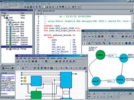
Yet success brings its own set of new challenges. For example: How do you integrate and debug IP delivered in a different HDL language? How can you train and integrate a new designer in your team to be productive sooner? How do you manage multiple synthesis tools as you attempt to target different devices or speed requirements? Every successful team has the experience to meet these challenges, but not necessarily the tools and methodology. This has prompted Mentor Graphics to develop a new Windows-based design environment for FPGAs, providing an easy-to-use, advanced-feature solution for FPGA design. Called ModelSim Designer, it combines the industry-leading capabilities of the ModelSim logic simulator with a built-in design creation engine. It is plug-in ready for the synthesis and place-and-route tools of your choice. The ability to easily manage the interconnection of the entire development flow gives FPGA designers improved productivity in design creation, simulation, debug, synthesis, and place-and-route - all from a single cockpit.
Flexible methodology
Designers can freely mix text entry of VHDL and Verilog code with graphical entry using block and state diagram editors. A single design unit can be represented in multiple graphical or abstract views. The management of compilation and simulation at all levels of abstraction is a single click away. This freedom to design according to the way you think extends to debugging - providing both graphical and text capabilities.
Alternatively, some teams opt for a purely graphical approach to ensure a consistent coding style. This also facilitates design re-use and maintenance. Graphical editors use an intuitive methodology that shortens the learning curve, improving the time required for new designers to become productive. This method is also useful for designers who are migrating to HDL methodologies or changing their primary design language.
Design implementation tasks are achieved through tight integration with the most popular FPGA synthesis and place-and-route tools in the industry. The user can either run these tools directly in the simulator graphical user interface (GUI) or externally, via scripts. Either way, the design data is maintained and used in a common and consistent way.
To improve throughput and the distribution of design tasks, an intuitive mechanism to compile the necessary vendor libraries for post-place-and-route simulation must be provided. With ModelSim Designer, the compiler detects which FPGA vendor tools have been installed and automatically compiles the necessary libraries as soon as the tool is launched. Engineers have access to the library compiler in the event that they want to compile additional vendor libraries.
Designers can automatically view or render diagrams from HDL code in block diagrams or state machines. When the design code changes, the graphical diagram can instantly be updated, ensuring its accuracy. This also helps designers understand legacy designs and aids in the debugging of current designs.
Integrating synthesis and place-and-route
The industry's popular synthesis tools from Mentor Graphics, Synplicity, and others can be integrated into this solution with pushbutton convenience. Place-and-route software from leading FPGA vendors is fully integrated. Place-and-route results, together with SDF information, are automatically re-read into ModelSim Designer after the process is complete, making it ready for post-place-and-route, gate-level simulation.
An intelligently-engineered GUI makes efficient use of desktop real estate. An intuitive layout of graphical elements makes it easy to step through the design flow. Wizards help set up the design environment and make the design process seamless and efficient. A memory window enables flexible viewing and switching of memory locations. VHDL and Verilog memories are auto-extracted in the GUI, delivering powerful search, fill, load, and save functionality. The memory window allows pre-loading of memories. All functions are available via the command line, making them available for scripting.
Creation wizards walk users through the construction of VHDL and Verilog design units, using either text or graphics. In the case of the graphical editor, HDL code is generated from the graphical diagrams created. For text-based design, VHDL and Verilog templates and wizards help engineers quickly develop HDL code without having to remember the exact language syntax. The wizards show how to create parameterisable logic blocks, testbench stimuli, and design objects. Novice and advanced HDL developers alike benefit from timesaving shortcuts.
A flexible and powerful project manager feature allows easy navigation through a design in order to understand design content. During compilation and simulation, the project manager stores the unique settings of each individual project and displays their hierarchy and dependencies in a separate pane.
Active design visualisation
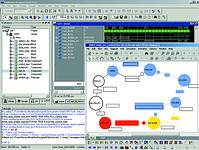
During live simulation, design analysis capabilities are enhanced through graphical design views. From any diagram window, simulations can be fully executed and controlled. Enhanced debugging features include graphical breakpoints, signal probing, graphics-to-text-source cross-highlighting, animation, and cause analysis. The ability to overlay live simulation results in a graphical context speeds up the debug process by allowing faster problem discovery and shorter design iterations.
ModelSim Designer offers an automated mechanism for testbench generation. The testbench wizard generates VHDL or Verilog code through a graphical waveform editor, with output in either HDL or a TCL script. Users can manually define signals in the waveform editor or use the built-in wizard to define the waveforms. Either way, it is intuitive, easy-to-use, and saves considerable time.
ModelSim Designer supports the entire FPGA design and verification flow from creation through simulation, synthesis, place-and-route, and post place-and-route simulation. It is a straightforward process, controlled from a single cockpit, with a large number of steps done automatically. This kind of coordinated efficiency increases productivity and design quality, helping FPGA designers meet the time-to-market and complexity challenges of high-performance FPGAs.
For more information contact Karlo Glorioso, ASIC Design Services, +27 (0)11 315 8316, [email protected]
| Tel: | +27 11 315 8316 |
| Email: | [email protected] |
| www: | www.asic.co.za |
| Articles: | More information and articles about ASIC Design Services |


© Technews Publishing (Pty) Ltd | All Rights Reserved
 printer friendly version