


Ref: z2801166m
The VisualAudio design and development environment is a new software tool for designing and developing audio systems. Its realtime-architecture is especially well-suited to the challenges of audio product development. This article briefly introduces VisualAudio, and then describes its framework, audio modules, and application to audio product development.
Audio product-development challenges
Today, audio system developers are faced with the increasing need to design complex audio systems-especially home audio/video receivers (AVRs) and automotive infotainment systems-both quickly and cost-effectively. Why?
* The number of discrete audio channels in normal use has grown from 2 to 4 to 5,1 - and most recently - to 7,1.
* The number of distinct, and sometimes competing, multichannel audio formats has been increasing rapidly - to include, among others, Dolby Pro Logic, Dolby Digital, DTS 5.1, Dolby Digital Surround EX, and DTS-ES.
* Products must interface with digital networks, such as the Media Oriented Systems Transport (MOST) bus, requiring network stacks, content encryption and decryption, and sample-rate conversion - all within the audio processor.
* Consumers have come to expect sophisticated post-processing features, such as spatialisation, automatic equalisation, and bass management - in both top-of-the-line and mainstream products.
To deal with these factors, developers are turning to digital signal processors (DSPs), because their programmability allows systems to be customised for specific market niches and applications. The SHARC processor family from Analog Devices (ADI) is particularly well-suited for this task, since it offers features such as large internal memory, floating-point precision, and high-performance computation units. The recently announced 'third-generation' SHARC processors take this one step further by integrating additional features that are specifically introduced to facilitate audio product design. These features include hardware sample-rate converters, encryption and decryption, a sophisticated digital audio interface, and an on-chip ROM containing multiple audio decoders.
The historical challenge faced by DSP users has been the development of software that makes optimum use of processor clock cycles and efficient use of memory. The long-used and laborious approach of hand-coding audio signal processing algorithms in assembly language has become less and less viable. This is particularly true when a large portion of the required effort goes into creating standard 'checklist' and 'me-too' functions instead of focusing on differentiating the product with value-added features. A better approach to developing audio product software was required.
To fulfil this need, ADI has developed a graphical environment - VisualAudio - as an aid to designing and developing audio systems that use the SHARC processor family. VisualAudio provides audio system developers with most of the software building blocks - together with an intuitive, graphical interface, shown in Figure 1 - for designing, developing, tuning, and testing audio systems.
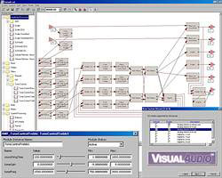
VisualAudio comprises a PC-based graphical user interface (GUI, the graphical tool), a DSP kernel (the framework), and an extensible library of audio algorithms (audio modules). Working in conjunction with ADI's VisualDSP++ integrated development and debugging environment (IDDE), VisualAudio generates product-ready code that is optimised for both speed, in millions of instructions per second (MIPS), and memory usage. By simplifying the process of developing complex digital signal-processing software, VisualAudio reduces development cost, risk, and time. As a result, audio-system developers are able to focus on adding value by differentiating their audio products from the competition.
At the core of VisualAudio is a realtime software architecture that handles audio I/O and post-processing. In order to be viable, the generated DSP code must be efficient in terms of MIPS and memory, and be flexible enough to handle a variety of audio product categories. The VisualAudio realtime architecture is described below, first the framework and then the audio-processing modules.
The framework
The framework is the portion of the DSP code that handles system initialisation, audio I/O, bit-stream detection, instantiating and calling audio decoders, and communication with the host. VisualAudio provides its users with examples of frameworks for AVRs and automotive audio systems. By writing platform-specific drivers, VisualAudio users can customise many aspects of the framework to address specific product requirements. In some cases, ADI will also make the framework source code available to VisualAudio users if internal changes are necessary for optimum performance.
Audio products have specific requirements that govern the design of the framework. Each audio product has two primary functions: (1) realtime audio processing, and (2) control of this processing. The time scales for these two functions are vastly different. The realtime processing (with all internal operations completed) must occur at the sampling rate, otherwise there will be unacceptable pops and clicks in the output audio. The control functionality can occur at a much slower rate, 10 Hz to 100 Hz, and still be acceptable. The bulk of the MIPS usage thus occurs within the realtime processing, while the bulk of the software complexity is within the control functions. In order to simplify product design and development, VisualAudio separates the realtime and control functions into separate threads. Efficiency is achieved by hand-optimised, realtime audio processing modules, while the complexity of control code is managed by allowing the developer to write it in C and run it in a separate thread.
Traditionally, two different approaches to audio processing have been taken. In stream processing, audio samples are processed one at a time as they arrive, while in block processing several audio samples are buffered and then processed as a group.
Each method has distinct advantages and disadvantages. Stream processing is efficient in terms of data memory, since no buffering of audio data is required. The major limitation of stream processing is that the overhead of multiple function calls cannot be tolerated. This forces the audio processing code to be written in-line, usually in assembly language. Such code is difficult to modularise and maintain.
Block processing requires additional buffering memory for I/O and scratch memory. Typical block sizes are in the range of 32 to 256 samples. Since many samples are processed at once, the overhead of function calls is amortised over a large number of samples. This leads to MIPS-efficient implementation - at the expense of additional memory - but is preferred, since structured programming methodologies may be employed. Block processing is also a natural fit to audio decoders that generate blocks of audio. For example, both Dolby Digital and DTS decoders generate audio in 256-sample blocks.
Block processing, the approach used by VisualAudio, has several additional advantages. All audio I/O within VisualAudio is double-buffered and managed using direct memory access (DMA). The processor receives an interrupt once per block - not once per sample - resulting in much less interrupt overhead than with stream processing. Also, by utilising the chained DMA capabilities of the SHARC processors, double buffering is managed by the DMA controller, significantly increasing the allowable latency when servicing an audio input/output (I/O) interrupt.
The VisualAudio framework delivers audio to the post-processing network in blocks. Certain restrictions are placed on the block size. First, it must be an even number, due to the single-instruction, multiple-data (SIMD) behaviour of some audio modules. Second, the minimum block size is eight samples - due to pipelining within some audio modules. Finally, in systems with an audio decoder, the post-processing block size must be a factor of the decoder block size. For example, with Dolby Digital, possible block sizes are 8, 16, 32, 64, 128, and 256 samples.
Audio I/O and buffering can be seen within the example of a VisualAudio automotive framework, shown in Figure 2. Audio arrives from either the MOST network or from A/D converters, and is separated into multiple streams. The primary entertainment stream is generated by the DVD player, and additional monaural streams are produced by the telematics system or by chimes. The DVD data first undergoes digital-transmission copy-detection (DTCP) decryption, and is then fed to the bit stream detector. The output of the bit stream detector is packed into blocks; when a complete frame of data is available, the audio decoder is executed. The DVD player generates its own sampling rate, which is distinct from the sampling rate used by the post-processing. Thus, the output of the audio decoder must pass through an asynchronous sampling-rate converter. This block converts all input data streams to a fixed output sampling rate. At this point, the audio post-processing is executed at a fixed block size of 32 samples. As a final step, the audio channels are fed to D/A converters or returned to the MOST network.
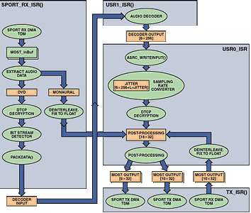
The automotive framework contains multiple audio decoders, only one of which is active at a time. To reduce decoder memory requirements, VisualAudio manages a decoder memory pool that is shared among all possible decoders. The output of the decoder is fed to the post-processing network; and this drives the D/A converters.
VisualAudio uses a simple interrupt driven kernel to manage multiple threads. For example, the sample automotive framework contains a total of six threads. From highest to lowest priority they are:
* Host communication - exchanges messages with the host - typically via SPI. Messages are buffered and interpreted within the DSP user control code (described below).
* Audio transmit interrupt - triggered by the serial port interrupt. Manages output DMA to the DACs - and formats data to be returned to the MOST network. Triggers audio processing within User Interrupt 0.
* Audio receive interrupt - separates audio into distinct streams. Performs DTCP decryption and packs encoded data into frames. When appropriate, triggers the audio decoder within User Interrupt 1.
* Audio processing (User Interrupt 0) - performs post-processing on a 32-sample block. The bulk of processing occurs within this thread.
* Audio decoder (User Interrupt 1) - executes the audio decoding function.
* DSP user control code (UCC) - runs whenever there are no interrupts active and serves as the main loop of the application. The user product's control functionality occurs within this thread.
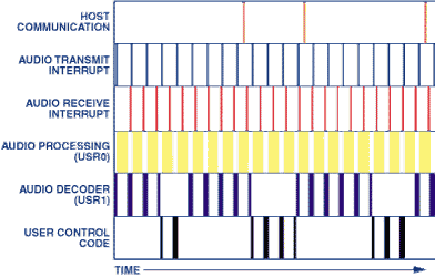
Typical thread activity within the sample AVR framework is shown in Figure 3. Each horizontal slice represents a different thread. The audio I/O, decoder, and the post-processing are run at regular intervals, and the UCC runs at the lowest priority. Note that the UCC might not be run for several milliseconds - while the processor is busy with audio processing.
VisualAudio partitions control functionality between the host microcontroller and the DSP. This partitioning is arbitrary, and can even support systems without a dedicated host microcontroller. As described above, the UCC executes at lowest priority - using any free cycles not consumed by the interrupt handlers. The UCC is called periodically by the framework with 'messages' and 'notifications'.
Messages are commands sent from the host microcontroller to the DSP. These commands are used to control audio processing (eg, 'Set the volume to -20 dB', "Set the bass tone-control to +3 dB") or to query the state of the audio processing (eg, 'Is the system limiting?'). The VisualAudio framework handles some commands internally, while the remainder are passed to the UCC. At each point in time, there can be only one pending message between the host and the DSP - and the DSP must send an acknowledgement after each command has been processed.
Notifications are generated asynchronously by the framework and occur under several conditions. The first notification occurs during system initialisation - before any realtime processing is enabled. System- or application-specific initialisation may be done at this time. A second notification, generated periodically at a rate of approximately 200 Hz, is used for control of the realtime audio processing, for example, automatic gain-control (AGC) calculations and updates. A final class of notifications is generated by the audio decoders in response to changes in the encoded bit stream. Notifications of this type occur when the sampling rate changes, the number of input channels changes, or if a cyclic redundancy-check (CRC) error is detected in the incoming bit stream. These notifications allow the UCC to make appropriate changes in the audio processing.
Since the UCC is pre-empted by realtime audio processing, it may not be executed until several milliseconds have gone by - as shown in Figure 3. VisualAudio includes several features that simplify writing a UCC that will be constantly subjected to interrupts. First, since the host-communication interface only allows a single host message to be pending between the host and DSP, there is no danger of overflowing a message buffer, or of host messages overwriting each other. Another feature is a notification queue, in which notifications of the same type overwrite each other. For example, if two sampling-rate notifications are generated closely spaced in time before the UCC is executed, then the UCC will only receive the second notification - the final sampling rate. Also, since there are a finite number of notifications, the notification queue is necessarily of finite length.
The UCC must also be carefully written for updating certain audio module parameters. Some module parameters, such as infinite impulse-response (IIR) filter coefficients, must be updated automatically without being interrupted by the audio processing.
Each VisualAudio framework has an associated XML platform file that describes the capabilities of the target platform to the VisualAudio application, and also contains a list of the source, object, and library files needed to build the executable. Software design and development usually begins on a readily available evaluation or development platform, such as an 'EZ-KIT Lite' evaluation kit from ADI, and then migrates to the actual target hardware once it is complete. VisualAudio's Change Platform Wizard automates the process of migrating software between hardware platforms.
The audio modules
VisualAudio contains a library of approximately 100 audio-processing modules that have been optimised for the SHARC processors. The modules, categorised by function, include volume controls, tone controls, filters, mixers, etc - enough functional types to develop a wide variety of audio products. These standard audio modules can be augmented by custom modules implementing proprietary post-processing features.
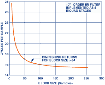
Figure 4 demonstrates the efficiency of block processing for a 10th order IIR filter - implemented as a cascade of five biquad filters. The number of operations per sample is plotted as a function of the block size. Most efficiency gains have been realized by a 64-sample block, with diminishing returns for larger blocks. For this filter, the core inner loop contains 21 multiply-accumulates (MACs) per sample; but by the use of SIMD instructions that operate on two pieces of data simultaneously, the loop is reduced to roughly 15 cycles.
Each audio module is described to the VisualAudio application by an associated XML file. This file contains a description of the module's in-memory data structure, memory allocation rules, input and output audio channel list, high-level interface variables (shown on the module's graphical representation, or 'inspector'), and design equations. The XML language consists of 'tags' that label structured data. For example, consider a simple audio module that scales a monaural signal by a fixed gain. This module would contain a single 'renderVariable' - amp - that specifies the gain to apply. Within the module's XML file, the variable 'amp' is described by the XML code shown below:
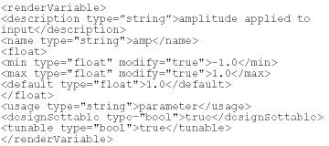
The description tag provides a short summary of the variable. The name tag indicates the variable name within the data structure. The variable is described as being floating-point, having a default range of [-1 +1] that can be modified, and a default value of 1,0. VisualAudio will treat this variable as a design-settable and tunable parameter, allowing it to be modified at design time, and later, during realtime tuning. This monaural fixed-gain example illustrates one of the many variable types that can be described by the VisualAudio XML format.
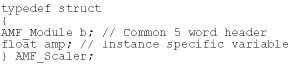
VisualAudio creates a separate data structure for each instance of an audio module within the post-processing layout. All data structures share a common 5-word header that describes the module's run-time interface to the framework. This is followed by module-specific parameters and -state variables. For example, the type declaration of the data structure for the scaler module described above is:
The audio processing functions within VisualAudio follow a uniform calling sequence. Each function is called with three arguments: a pointer to the instance data structure, a pointer to an array of input and output buffer pointers (input buffers first, then output buffers), and an integer specifying the block size. Continuing the example of the scaler, its realtime processing function is defined below.
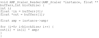
Note that this example is written in C to clarify its description. The actual 'render' function included with VisualAudio is written in optimised assembly language for speed of execution.
Summary
The complexity of digital signal processing software within audio products continues to increase. To address this, Analog Devices has developed VisualAudio, a graphical audio system design and development environment. VisualAudio simplifies audio product design and development by providing developers with many of the key software building blocks found in audio systems, managed with an intuitive graphical interface. The VisualAudio realtime architecture is flexible enough to support a variety of product types and is also efficient in terms of MIPS and memory. The overall VisualAudio tool-chain jump-starts product development; reduces development cost, time, and risk; and allows engineers to focus on innovation and product differentiation.
For more information contact Stephen Silberman, Analog Data Products (Division of Avnet Kopp), +27 (0)11 809 6100, [email protected]


© Technews Publishing (Pty) Ltd | All Rights Reserved
 printer friendly version