


Your system engineers define the specifications, which software engineers must then interpret to write code. How do you ensure that the system will correspond to the original concept?
Your powertrain design team wants to reduce testing on expensive engine hardware. How do you minimise test iterations while optimising system performance?
As a semiconductor designer, you work with multiple R&D teams to design efficient implementations of complex audio codec algorithms. How do you enable these teams to collaborate and share design drafts?
Problems like these, all too familiar to embedded systems and electronics engineers, can jeopardise project results. In independent industry studies, Jerome Krasner discovered that 51% of embedded design projects finish an average of 3,5 months behind schedule.
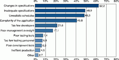
Specification changes are a major cause of project delay. Poorly communicated specifications, planning errors, and project complexity have a similarly profound effect on productivity (Figure 1). These problems are common in traditional development methods, which rely on document-based specifications that can be ambiguous and easily misunderstood.
Working with model-based design
Model-based design for embedded systems addresses all the key factors that delay a project, including changes in specifications, project complexity, and unrealistic schedules, because design teams work from a single Simulink model of the entire system and its environment. Engineering teams use the model throughout the development process - from requirements capture and design to implementation and test.
This model becomes an 'executable specification' and includes all the information needed to specify the software or hardware implementation, including fixed-point and timing behaviour. Simulation is used to show that the model is complete and works correctly. All the code and test benches for final system testing, verification, and deployment can be automatically generated from the model, saving time and avoiding the introduction of errors.
Model-based design reduces the complexity of large-scale system development by letting multiple design teams work in parallel to refine and optimise subsystem designs. As each subsystem is finalised, it can be incorporated into the overall system model.
Executable specifications
Graphical representations are at the heart of model-based design, starting with requirements gathering.
Traditionally, system engineers capture requirements in a paper specification that design engineers must interpret. Paper-based specifications shared among different teams are easily misinterpreted, and hand-written code increases the risk of propagating errors throughout the design process.
By sharing the same executable specification, design teams can bypass hand-written documentation, eliminate ambiguity and misinterpretation of specifications, and clearly communicate critical issues and decisions, including requirements changes.
Design with simulation
Developing hardware prototypes is costly and time-consuming. Design engineers are often unable to create multiple prototypes to explore design optimisations. Consequently, even designs that meet specifications may not be fully optimised.
Because the model provides a comprehensive description of the design, the development team can simulate its performance in a software environment, reducing the need for costly hardware prototypes. As a result, they can find and correct problems much earlier in the design process, refine the design, automatically update the executable specification, and perform more design tradeoffs in a shorter period of time.
The model provides continuity in the design and development process and can be used to test any optimisations proposed by the implementation team. As a result, the final product will be much closer to the original design.
Implementation with automatic code generation
The transition from design to implementation traditionally involves a design engineer transferring a set of plans to an implementation team. As with the transition from specification to design, misinterpretation at this point can cause errors.
Because the model is an executable specification, engineers can automatically generate code from the model for realtime prototyping and deployment in the target system. Automatic code generation enables engineers to eliminate hand-coding errors and reduce the time spent on writing and testing code. Any problems in the code are easily corrected by making changes to the model and regenerating code. This ensures that design specification integrity between the model and the code is maintained.
Continuous test and verification
Test and verification is traditionally the final step before product delivery. When design teams discover problems at this late point in the development process, they face two equally unattractive options: delay the product ship date or ship a sub-standard product.
The system model provides a 'golden' reference that can serve as the test bench for the hardware or software implementation. Like the model, the code can be tested and verified at any point in the design and simulation process. Because the Simulink model represents the exact system requirements, teams can use the design as a reference for generating test signals, troubleshoot and trace problems early in the development process, and streamline the verification of hardware or embedded software designs. Engineers can update the model and regenerate the code to realign the design with the specifications, reducing troubleshooting and correction time from months to days, or even hours.
The value of model-based design
By enabling engineers to design components in a complete system context, model-based design helps eliminate ambiguities and conflicting requirements from embedded system development. System designers can begin evaluating software and hardware designs without waiting for prototype products. Project planners can more realistically assess the resources required to implement the system-level design. The result is more innovation, improved product quality, and reduced time to market.
| Tel: | +27 11 325 6238 |
| Email: | [email protected] |
| www: | www.optinum.co.za |
| Articles: | More information and articles about Opti-Num Solutions |


© Technews Publishing (Pty) Ltd | All Rights Reserved
 printer friendly version