


With the growth of optical fibre networks occurring at an almost exponential rate, the demand for efficient and cost-effective optical cable management has never been more important than it is today.
Ever-evolving optical networks demand access to backbone networks with an optical distribution frame (ODF) that can economically service less than a hundred terminations today, yet can be easily scaled up to service over 2000 tomorrow.
The ODF must protect cable yet provide easy accessibility. It must minimise cable motion when accessing circuits. It must neatly store ample slack for each connection while providing full radius bend protection. And its design must be efficient, flexible, and based on what customers really want.
No less important, this ODF must offer industry-leading termination density, exceptional cable management, cable protection, and ease-of-use for optical interconnections in both central offices and private networks.
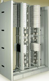
Development of a quality ODF requires thorough research and analysis of both existing fibre distribution solutions and customer feedback on future optical distribution needs. With that research and feedback in mind, state-of-the-art design techniques are required to create an optical distribution frame that makes a truly significant contribution to the optical distribution marketplace. A new design as shown in Figure 1 meets all these needs today.
When evaluating an ODF for your facility, keep the following traits in mind:
* Frame: An ODF frame should use a standard 600 x 600 mm (W x D) for ETSI applications. It should include an integrated and versatile system for storing slack for cables entering the frame, whether from the top or the bottom. Module installation, multifibre cabling, and patching should all be accessible from the front of the frame so minimising the number of personnel required to install and maintain the system.
* It is all in the tray: One of the most important considerations when selecting an ODF is finding one whose cable connectors are housed in separate trays that slide or pivot out for easy access. While every ODF provides this capability to some extent, it is equally vital that there is automatic compensation for cable slack that prevents cable movement and tension when trays are opened and closed. Trays, as well as the entire frame, must also incorporate full 30 mm bend radius protection and require no fishing of cables.
Each tray should contain a small number of connections to minimise the potential for accidentally disturbing one connection while servicing another. Trays not in use should remain isolated and out of the way. Adapters mounted in a staggered configuration will promote a sure, certain grip of individual connectors while minimising the possibility of disturbing those adjacent.

* Cable protection: An ODF that leaves cables hanging loose and in disarray is damage waiting to happen. An ODF should leave no cable exposed at service aisles where it is vulnerable to damage from tools, equipment carts, and other maintenance activities.
While most ODFs can easily route 2 mm cable, do not overlook how it handles stiff and difficult-to-weave IFC cable. An ODF that runs robust IFC cable down the back of the frame where it is easy to route, access, and tie off is a definite plus.
A well-designed ODF with well-defined pathways also reduces the amount of exposed cable inside the frame, thereby preventing its tangling, stretching, and movement. Carefully placed cable waterfalls, channelled storage spools, and cable management tabs will manage fibre cable while maintaining ease of access.
Make sure every curve and transition incorporates a 30 mm bend radius to meet Telcordia specifications and also make the frame ready for increased bandwidth demands required by advanced technologies such as DWDM, L-Band wavelengths, and 3G wireless systems.
* Flexible configuration and cabling: You should be able to easily configure and optimise an ODF for either interconnect or cross-connect applications, and ideally it should also handle on-frame splicing of outside plant and inter-facility cable for both stranded and ribbon fibre.
Look for an ODF with the shortest possible jumper length between the two farthest-apart connections; a short length means less cable to buy and less stored in the frame; 4,5 m is the current minimum length for this connection.
Make sure the ODF is compatible with a robust cable management system such as Telect's WaveTrax Cable Management System.
* Termination density: You will want an ODF that can accommodate more terminations than you think you will need. While some ODFs can handle around 1000 terminations, others can handle over 2300. Also consider the number of patch and splice terminations the frame is capable of: look for over 700 for maximum expansion capability. Whatever the claimed capacity, make sure that number can be attained in a standard footprint. If the ODF offers total front access, that eliminates the need for wide service aisles for rear jumper access, so you can further improve density and use of floor space by positioning frames closer together.
* Cable access and designation: Make sure all patch cords can be accessed from the front. Ensure inter-bay jumpers can run through upper and lower troughs, and that both troughs are front-accessible. Look for easy access to riser/network/patch cord interconnections and cross-connections, and for well-defined pathways to all trays. Look for diverse routing options for reduced cable congestion; an ODF with a split vertical cable storage channel, for example, significantly minimises cable congestion.
Generous circuit designation areas enable fast and accurate circuit identification. Look for at least two square inches of designation area per port.
* Flexible mounting options: Connector trays normally come grouped, a dozen or so to a module. You should be able to mount modules at multiple points along the frame's vertical mounting rails and with gaps between modules for easy separation of portions of the frame as 'working' or 'protect,' or to otherwise match your network's operating practices. Conversely, you should also be able to install modules directly adjacent to each other for maximum density. Look for variable module sizes handling from 72 to 144 fibres to enable matching of module sizes to incoming fibre counts.
* Laser light eye safety: As laser power increases in the future, it becomes increasingly important that ODFs incorporate inherent protection against stray laser light. Look for a tray design that incorporates some kind of 'beam stop' to protect technicians from laser eye damage.
* System weight, integration, and expansion: Heavy-duty does not have to mean heavyweight. In many network deployments, floor load limit is a constraining factor. However lightweight, high density frames are available on the market - ensure it is still in a NEBS-certified 600 mm frame with Zone 4 earthquake reliability.
Regardless of weight, the frame should be structurally reliable and available in all industry standard footprints so it can integrate seamlessly into floor and cable management layouts, whether new or existing. An ODF should install easily with no onsite modification of components.
A company that can provide design, configuration, and implementation services to accompany the ODF can greatly simplify and accelerate your ODF planning and integration by delivering modules or complete frames pre-configured to your exact specifications.
Make sure the frame has network element modules, intra-facility cable modules, patch and splice modules, and value-added modules available for future requirements.
* NEBS certification: Finally, look for an ODF certified to NEBS requirements for temperature, handling, humidity and altitude, fire resistance, earthquake and vibration, optical signal compatibility, electrical safety, and traceability.
| Tel: | +27 10 595 1821 |
| Email: | [email protected] |
| www: | www.comtest.co.za |
| Articles: | More information and articles about Comtest |


© Technews Publishing (Pty) Ltd | All Rights Reserved
 printer friendly version