


The OTDR is a critical tool in the characterisation and certification of fibre-optic links (multimode and singlemode LAN/Ethernet). When choosing an OTDR, it is important to select the specific OTDR performance and features needed to qualify these links accurately and to the required specification/standard.
There are a wide number of OTDR models available, addressing different test and measurement needs - from very simple fault finders to advanced OTDRs for link certification. To make the right choice, five fundamental parameters must be considered when purchasing an OTDR, as selecting a unit simply based on overall performance and price will lead to problems if the selected model is inappropriate for the application. A solid understanding of these parameters will help buyers make the right choice for their specific environment, and thus maximise productivity.
The key specifications that should be considered when purchasing an OTDR are the following:
* Dynamic range.
* Dead zones (attenuation and event).
* Sampling resolution.
* Ability to set pass/fail thresholds.
* Post-processing and report generation.
Dynamic range
This specification determines the total optical loss that the OTDR can analyse; ie, the overall length of fibre link that can be measured by the unit. The higher the dynamic range, the longer the distance the OTDR can analyse. The dynamic range specification must be considered carefully for two reasons:
1. OTDR manufacturers specify dynamic range in different ways (playing with specifications like pulse width, signal-to-noise ratio, averaging time, etc). Therefore, it is important to understand them thoroughly and avoid comparing apples and oranges.
2. Having insufficient dynamic range will result in the ability to measure the complete link length and, in many cases, affect the accuracy of the link loss, attenuation and far-end connector losses. A good rule of thumb is to choose an OTDR whose dynamic range is 5 to 8 dB higher than the maximum loss you will encounter.
For example, a singlemode OTDR with a dynamic range of 35 dB has a useable dynamic range of around 30 dB. Assuming typical fibre attenuation of 0,20 dB/km at 1550 nm and splices every 2 km (loss of 0,1 dB per splice), a unit such as this one will be able to accurately certify distances of up to 120 km.
Comparatively, a multimode OTDR with a dynamic range of 26 dB has a useable dynamic range of around 21 dB. Assuming typical attenuation of 0,5 dB/km at 1300 nm and two connector losses of about 1 dB each, this unit would be able to accurately certify distances of up to 38 km.
Dead zones
Dead zones originate from reflective events (connectors, mechanical splices, etc) along the link, and they affect the OTDR's ability to accurately measure attenuation on shorter links and differentiate closely spaced events, such as connectors in patch panels, etc. When the strong optical reflection from such an event reaches the OTDR, its detection circuit becomes saturated for a specific amount of time (converted to distance in the OTDR) until it recovers and can once again measure backscattering accurately. As a result of this saturation, there is a part of the fibre link following the reflective event that cannot be 'seen' by the OTDR, hence the term dead zone.
When specifying OTDR performance, analysing the dead zone is very important to ensure the whole link is measured. Two types of dead zones are usually specified:
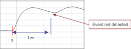
1. Event dead zone: This refers to the minimum distance required for consecutive reflective events to be 'resolved'; ie, to be differentiated from each other. If a reflective event is within the event dead zone of the preceding event, it will not be detected and measured correctly. Industry standard values range from 1 m to 5 m for this specification.

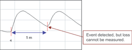
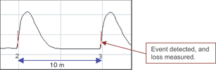
2. Attenuation dead zone: This refers to the minimum distance required, after a reflective event, for the OTDR to measure a reflective or non-reflective event loss. To measure short links and to characterise or find faults in patchcords and leads, the shortest possible attenuation dead zone is best. Industry standard values range from 3 m to 10 m for this specification.
Sampling resolution
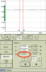
Sampling resolution is defined as the minimum distance between two consecutive sampling points acquired by the instrument. This parameter is crucial, as it defines the ultimate distance accuracy and fault-finding capability of the OTDR. Depending on the selected pulse width and distance range, this value could vary from 4 cm to 5 m for EXFO's FTB-7000D series.
Pass/fail thresholds
This is an important feature because a great deal of time can be saved in the analysis of OTDR traces if the user is able to set pass/fail thresholds for parameters of interest (eg, splice loss or connector reflection). These thresholds highlight parameters that have exceeded a warning or fail limit set by the user and, when used in conjunction with reporting software, it can rapidly provide re-work sheets for installation/commissioning engineers.
Report generation
Report generation is another major timesaver, as post-processing time can be reduced by up to 90% if the OTDR has specialised post-processing software allowing fast and easy generation of OTDR reports; these can also include bidirectional analyses of OTDR traces and summary reports for high-fibre-count cables.
| Tel: | +27 12 349 1341 |
| Email: | [email protected], [email protected] |
| www: | www.lambdatest.co.za |
| Articles: | More information and articles about Lambda Test |


© Technews Publishing (Pty) Ltd | All Rights Reserved
 printer friendly version