


Engineers and lighting designers have recognised for some time that a shift to LEDs as the primary light source for general lighting applications is just around the corner. Consumers, too, are beginning to become aware of this transition, with the first LED lamps for domestic use beginning to appear in the retail chain.
Expectations are high; having been persuaded, then forced by legislation to abandon the incandescent lamp in favour of higher-efficiency products, users’ experience with compact fluorescent lamps was often less than satisfactory. Now, the message to those consumers is that LEDs will deliver long life, durability and efficiency, together with a pleasing spectral performance.
General lighting – provision of ambient illumination for homes, offices and public spaces – is, in fact, somewhat lagging behind the pace of adoption of LEDs in a wide range of other applications. Some examples include automotive lighting for brake lights, running lights and, just starting to appear, headlights; architectural colour effect lighting; industrial, outdoor and street lighting; traffic and railway signals; and backlighting for LCD panels in televisions and monitors. In some of these applications, efficiency is paramount, by far the most important reason for moving to LEDs. In others, the main reason for their adoption lies with the flexibility given to designers of light fittings, when they no longer have to provide access to replace bulbs with limited life. In other cases it is the degree of control over the light, in terms of both hue and intensity, that appeals to lighting engineers.
Just as the CCFL changed the notion of a light source from a device that simply plugged into a supply, to one that required its own driver electronics package, so the advent of LEDs implies an associated page of driver and, in many cases, control circuitry. LEDs require constant-current drive. While a linear voltage regulator configured as a constant-current source may be acceptable for low-intensity applications, any design that focuses on high light output and efficiency will demand a switch-mode supply.
A number of common power supply topologies are useful for driving LEDs, including buck, boost, charge-pump, SEPIC, buck-boost and flyback, each with their own advantages in different circuit configurations. Many vendors including Microchip Technology offer dedicated driver ICs. A microcontroller can add intelligence to an application when paired with a driver IC; or the MCU can integrate the LED drive function, generating the drive waveforms and timing.
In the case of an application such as architectural effect lighting, the scope for using an MCU for setting precise levels to drive differently-coloured LEDs is clear. Perhaps less obvious is the issue of managing the production of white light, where an MCU not just adds intelligence, but is essential.
Single-source white LEDs are in fact blue light emitters, in which some of the blue light is used to energise a mix of phosphors that emits light in a range of colours from red through to green, to yield an overall white output. Many white LEDs cannot yield a high colour rendering index (CRI), which is a measure of the ability of the light source to faithfully reproduce all colours. Systems with a better quality of white light can be created by mixing the light from two or more LED colours. The light output from each colour source drifts with age and temperature. This can be corrected and the overall light output – specific colour or correlated colour temperature (CCT) – held constant by a feedback loop using a light sensor and a small MCU.
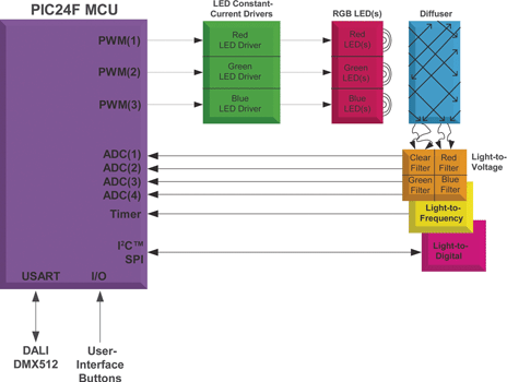
A range of small, inexpensive light sensors is available in the market. They typically comprise selectable colour filters – red, green, blue or none (white) – and a light-level sensor. The light sensor can supply intensity-level data to the MCU in a variety of ways. Light-to-voltage sensors send voltage levels to an analog-to-digital converter (ADC). Light-to-frequency sensors provide a variable frequency output, where the frequency is proportional to the amount of light. The pulse output from these sensors can be accumulated in an MCU timer to determine the light level. Light-to-digital sensors typically have a serial digital interface, such as I²C. Each type of sensor interface has unique advantages and requires different MCU resources (Figure 1).
In a complete closed loop colour-control system, the MCU must read the component colours from the light sensor, calibrate the light sensor output, and adjust the output of the individual LED drivers to achieve the desired colour. The choice of driver technique will depend on factors such as efficiency requirements, input voltage range and the number of LEDs used.
Different methods may be used to control the driver output. The MCU can generate an analog reference voltage using a digital-to-analog converter (DAC) or a digital potentiometer, and that voltage will directly set the LED drive current. Alternatively, in an all-digital control chain, the MCU can provide pulse-width-modulated (PWM) signals that are used to modulate the driver output. The PWM signal can be used to enable/disable the driver itself, or it can be used to control a switch that disconnects the LEDs from the driver output.
If PWM control is used, the PWM frequency is chosen to be high enough so that the human eye cannot detect any flickering. This approach can be helpful if the application demands maximum efficiency; many LEDs deliver their peak efficiency (light output for a given current) at, or close to, their rated maximum. Delivering reduced light levels by a pulsed drive at the peak current level, rather than by a reduced constant current, will be more efficient.
The designer must decide how much control resolution is required in a colour control system, in order to select a MCU with the proper peripherals. For a light-to-voltage sensor, the measurement resolution of the on-chip ADC will be important. A light-to-frequency sensor requires an MCU timebase that can be incremented using an external clock. Light-to-digital sensors will require an appropriate serial communications interface peripheral.
An MCU with multiple PWM peripherals is useful for controlling the individual LED drivers. In high-resolution colour control systems, a PWM peripheral with 16 bits of control resolution or better is preferred. Serial communication peripherals, such as UARTs, SPI, I²C, LIN and USB, enable input/output control and display functionality.
The designer will also have to determine the sample rate at which the control loop operates, and choose an MCU with appropriate computational resources. If the system is primarily concerned with maintaining a constant-white output as the LEDs age, then a relatively infrequent update rate will be required. LEDs of different colours will typically follow different light output curves as they age; but they will also do so in response to different drive levels.
In variable-brightness, or dimming, applications, the colour-control loop must update to keep pace with the rate of change of brightness. One of the most demanding applications of this type is in selective dimming of LCD backlighting. To enhance contrast in dark areas of a television picture, the backlighting in those areas is dimmed; but it must be maintained as a pure white in order that the LCD panel can continue to show the correct picture hue. In this case, a control loop update rate appropriate to the TV frame rate is required.
A device like the PIC24FJ16GA002 is a good candidate for the MCU in a colour-control system. The PIC24 device is available in small 28-pin packages with program memory ranging from 16 to 64 KB and provides serial communication interfaces, 10-bit ADC and 5 PWM channels. The 16-bit MCU core easily handles the mathematics associated with the sensor calibration and colour control.
The data output from the light sensor must be calibrated against a reference in order to provide consistent results. The calibration process uses a chroma meter to mathematically correlate the output of the different colour LEDs and the spectral response and sensitivity of the light sensor to a standard colour coordinate system, established in 1931 by the International Commission on Illumination (CIE), the CIE XYZ colour space. The calibration process generates a matrix of coefficients that must be stored in non-volatile memory with the luminaire system and will be used to determine the difference between correlated and the desired output each pass through the control system.
Once calibrated, the MCU compares sensor data against desired coordinates on the CIE chromaticity plot and sets the drive values on each output channel until the correct CCT is achieved. As the control loop is operating in a dynamic environment, it is appropriate to use servo-type techniques; each channel has a PID (proportional-integral-derivative) algorithm that adjusts sensor data with the calibration values, evaluates the difference to target setpoint and adjusts the output channels accordingly.
As with any other closed-loop PID architecture, the algorithm runs continuously to reduce the error until the output CCT matches the setpoint CCT. PID coefficients can be tuned to maximise the response of the system, but the rate of convergence to the setpoint depends on the MCU’s efficiency in processing the mathematical demand. As noted previously, some colour control systems may require faster processing and response time than others.
Systems that require an adjustable light source or one with high CRI (ability to render colours faithfully to the human eye) can have a wide range of user control requirements. A medical device with a graphical LCD display may have a tuneable LED backlight requiring the MCU to communicate to the LCD over SPI, as well as a touch-screen interface for adjusting the CCT and brightness. General illumination lighting for a commercial display case may require control from a central panel or computer to automatically adjust brightness, CCT and on/off based upon the time of day.
Communication between these devices may be implemented using hard-wired serial bus protocols that are common in the lighting domain, such as DALI (Digital Addressable Lighting Interface, IEC 929) or DMX512 (a standard often seen in stage lighting and effects systems). Others may use a custom interface over USB or Ethernet. When retrofitting advanced lighting systems to existing buildings, lighting designers are increasingly turning away from hard-wired infrastructure to wireless communications and a protocol such as ZigBee for control. An MCU with flexible peripherals is an ideal host to implement the communication and user interfaces for these types of lighting applications.
Reference
Microchip Application Note # AN1257, ‘Closed loop chromaticity control: Interfacing a digital RGB colour sensor to a PIC24 MCU.’ The application note and more information about ‘MCU Peripherals useful for LED Colour-Control Systems’ can be found under ‘Colour Control Solutions’ at Microchip’s online Intelligent Lighting Design Centre, www.microchip.com/lighting.
| Email: | [email protected] |
| www: | |
| Articles: | More information and articles about Tempe Technologies |


© Technews Publishing (Pty) Ltd | All Rights Reserved
 printer friendly version