


Process capability is defined by DIN ISO 21747:2006 as a statistical estimate of the consequence of a characteristic of a process which is verifiably kept under control, wherein the estimated value describes the capability of the process to affect the characteristic such that it fulfils its respective requirement[1].
Sauer[2] goes into the subject of the quality capability of processes in great detail.
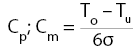
Process capability and machine capability describe the potential capability of a process or machine to produce a certain characteristic in a constant fashion within specified tolerance limits. Capable machines are a prerequisite for capable processes. Machine capability only takes the capability of the machine into consideration. The capability of a process/machine can be numerically described through the use of generally accepted capability indices.
Process capability, machine capability:
Critical process capability, machine capability:
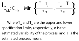
Due to the fact that process capability depends upon the capability of the utilised production machines, higher numeric requirements are specified for machine capability; in general, a capability value of Cmk > 1,67 is required of machines [Sauer, p. 285].
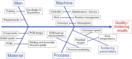
Problems become plainly apparent right from the start when attempting to ascertain capability coefficients for the reflow process. Which measurable characteristics can be defined? The Ishikawa diagram shown in Figure 1 demonstrates that the quality of the soldering results depends upon a great variety of influencing factors, and that the impact of the machine (reflow system) accounts for only a small portion of overall influence.
Soldering defects such as voids are thus unsuitable for determining the machine capability of a reflow system. Contradicting effects make it impossible to unequivocally allocate temperature as a machine parameter to soldering defects as a quality characteristic. The example provided in Figure 2 demonstrates this in an impressive fashion.
![Figure 2. Voiding relative to peak temperature<sup>[3]</sup>](articles/Dataweek - Published by Technews/dw7759b.jpg)
Results presented by Wohlrabe[3] in the ‘Pores’ expert database reveal that mean void content in BGAs increases as peak temperature rises, whereas it decreases in silicon chips.
Temperature, conveyor speed and, if applicable, temperature differences are all possible candidates as measurable characteristics. As opposed to mechanical systems, the fact that there is direct interaction between the reflow system and the measuring device (test board) must be taken into consideration in the thermodynamic world of reflow soldering. This interaction is depicted in Figure 3.
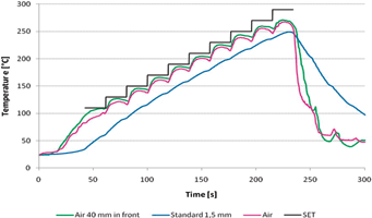
The graphic shows reflow system settings, atmospheric temperatures at the conveyor level 40 mm downstream from the test board (Air 40 mm downstream) and at the middle of the test board (Air), as well as the temperature of a standardised mass. It is apparent that the atmospheric temperatures differ from each other. The test board absorbs heat energy from the environment, thus resulting in a lower temperature at the middle of the test board (Air) than at the same level downstream from the test board.
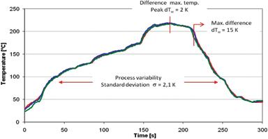
This interaction makes it extremely difficult to use temperature differences as a measurable characteristic. For example, the width profile of a reflow system is shown in Figure 4. Temperature differences amongst maximum temperatures (dT = 2 K; left, middle, right) on the test board differ considerably from the maximum temperature differences demonstrated by the measurement curves (15 K). This results from just a minimal time difference in cooling characteristics. For this reason, it is advisable to ascertain absolute temperatures on standardised test boards for the determination of reflow system machine capability coefficients.
The next difficulty arises in establishing tolerance limits. All too frequently, experience from the field of mechanical engineering is used to this end, and excessively tight tolerance limits are specified which cannot be adhered to in light of the thermodynamic circumstances which prevail in the field of reflow soldering. Consequently, Table 1 should be used as a basis for discussing which elements will determine overall tolerance width.
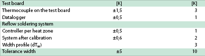
Temperatures are determined by means of a test board to which type K thermocouples with a limit deviation of ±1,5 K are attached in accordance with IEC 584. Data are recorded by a data-logger during the measurement procedure with a measuring accuracy of ±0,5 K. The test board and the reflow soldering system interact with each other, which means that the repetition accuracy of the reflow system must also be taken into consideration.
The controllers for the individual heat zones have an accuracy of ±0,5 K. The internal temperature measuring section of a reflow soldering system can be calibrated, after which it adheres to a tolerance of ±0,6 K. However, calibrating a reflow soldering system is very time consuming (as many as 12 work hours), so that many systems are not calibrated for cost reasons. But test boards are usually calibrated, so that at least one calibrated value is usually calculated into the tolerance width.
Finally, heat transfer homogeneity must also be taken into account, which is represented by the width profile’s numeric value (dTw). All in all, this often results in a tolerance width which is quite large in comparison with mechanical systems. In actual practice, however, this type of procedure has turned out to be a solid basis for ascertaining capability values for the reflow process. Thanks to CCS (capability control system), Rehm Thermal Systems’ reflow soldering systems are equipped with an automatic system which eliminates the need for manufacturing facilities to conduct extremely time consuming, manual determination of capability coefficients.
References
[1] DIN ISO 21747:2006, Statistical methods – Process performance and capability statistics for measured quality characteristics, DIN Deutsches Institut für Normung e.V. (German Institute for Standardisation), p. 24.
[2] W. Sauer, Prozesstechnologie der Elektronik, Hanser Verlag 2003, p. 282 ff.
[3] H. Wohlrabe, TU Dresden, Expertendatenbank AK Poren 2010 (‘Pores’ expert database).
For more information contact Truth Electronic Manufacturing, +27 (0)31 822 8555, [email protected]
| Tel: | +27 31 822 8555/6 |
| Email: | [email protected] |
| www: | www.truthelectronics.co.za |
| Articles: | More information and articles about Truth Electronic Manufacturing |


© Technews Publishing (Pty) Ltd | All Rights Reserved
 printer friendly version