


As demand for conformal coating protection becomes more prevalent in consumer handheld devices, traditional market segments including defence, aerospace and automotive electronics are being displaced by applications requiring smaller, more intricate and precise application processes.
Processes requiring micro application of conformal coatings in small, densely populated regions where volume, accuracy and process control are crucial, have become increasingly prevalent.
These requirements present manufacturers a new set of challenges as they adapt to innovative methods that satisfy these applications. To achieve optimum results, the process must address consistency in the coating material, substrate position, dispensing application, and provide process control and quality feedback. Previously, many of these parameters could be controlled via manual viscosity confirmation, mechanical tooling and periodic quality checks. However, as coating areas and tolerances are now tighter than ever, advanced controls are required.
Viscosity stabilization
It is not unusual for a coating chemistry’s viscosity to vary ±5%–10% from batch to batch. Factoring in any changes over time (due to temperature, pot life, shelf life or fluctuations due to moisture exposure) assures that obtaining a consistent product to dispense or spray can be a difficult endeavour.
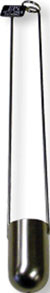
Measuring consistency also presents a series of challenges. Traditionally, viscosity could be monitored via a Zahn cup reading. A Zahn cup is typically a stainless steel cup with a precision hole machined into the bottom. The cup determines the viscosity of the liquid by dipping and filling it completely with the fluid. When lifting the cup out of the coating, the operator would measure the time it takes for the liquid stream to break. This process is still widely used and results in a coating having a Zahn cup reading or ‘viscosity’ of ‘x’ seconds. As long as the reading fell within a target range, the process was acceptable.
This method checks viscosity only as often as the readings were taken. No feedback or constant control mechanism was in place to assure repeatable results throughout the process.
The most common material issue tends to be temperature. Temperature swings can adversely affect a coating’s nominal viscosity. This is often anticipated by obtaining a temperature vs. viscosity curve from the material manufacturer. To counteract this issue, viscosity can be tightly managed via a temperature control system. This option is a multifaceted process whereby the coating temperature is consistently maintained in the material reservoir, regulators and fluid lines. This is easily accomplished with heated components throughout the fluid delivery system where the temperature can be controlled within 2°C.
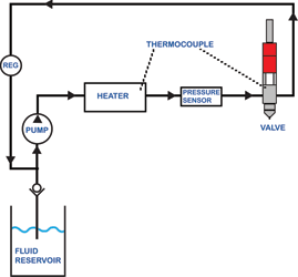
The second step in the viscosity management process is to recirculate the coating. Once heated, the coating should remain in constant circulation to assure uniformity. A servo controlled gear pump can move the material throughout the fluid lines and back to the tank.
Precise coating applications
Once the coating chemistry is stabilised, it is critical that both the board position and application valve are reliable. This requirement is magnified in a micro coating application as the coverage area and volume are minute.
Wide area coating operations employ a broad range of coating applicator combinations. In micro coating processes, the valve set becomes much more focused. Correspondingly, traditional board tooling (pneumatic stop, pin locators, and lift and locate solutions) may have too much variability to meet the high demands of positional accuracy for micro coating applications.
Improving deposit location
Robotic coating systems are highly repeatable with average accuracy within &plumn;0,025 mm. Long term, maintaining accuracy is a key element in any coating process. Almost exclusively, equipment manufacturers utilise gantry systems featuring precision ball screw slides driven by brushless DC servo motors across three or four programmable axes. Servo control, as opposed to stepping motors or pneumatic movement, improves positional accuracy and utilises optical encoders to provide constant feedback.
Even with the most precise robotic solution in place, variability in the substrate position can adversely affect the coating process. While the robot will dispense at the same spot in space repeatedly, assuring the desired components are in the appropriate position presents another challenge. Traditionally, securing a board was conducted by simple pneumatic stop arms. Improvements can be made by employing pin locators or adding a lift and locate process, among other solutions. While this can assure the board is in the appropriate location, there is no positional verification.
Recently, machine builders have begun to employ technology typically used for applications like underfill, wire bonding and encapsulation to improve accuracy in their coating processes. Most common is the use of active vision systems with fiducial correction in the XY plane. Active vision systems provide component level accuracy and correct the application process to account for variation. In addition, the user may benefit from utilising the image and crosshair generator to ease programming (overhead work area image) and inspection.
Micro-coating valve technology
The ability to dispense very small beads and dots has existed for decades, though their implementation into coating processes has been a fairly recent development. What began as repackaging of rapid actuating dot valves as ‘jetting’ or ‘streaming’ technology, has spurred the development of a series of application heads capable of applying coating in faster, more controlled deposits. These methods, coupled with ever improving spray technology, have opened the door to new opportunities for equipment suppliers and provided more flexibility to circuit board manufacturers.
Micro valves apply streams of coating from 3–8 mm above the circuit board surface to create precise dots and beads. These valves can accurately apply coatings from a common working height so z-axis motion is not required. This process is often called ‘non-contact’ although any typical dispensing process also meets this general definition. Think of a typical dot or bead dispensing process, but the orifice is much smaller, precisely milled (usually stainless steel) and reduces dead space. The orifice is rugged and repeatable so positional issues resulting from flexible 1–2 mm long plastic or thin steel needles are eliminated.
Some micro valves pulse rapidly to create dots. Beads are formed by moving the robot and repeating the dot procedure to form a line that will, in theory, flow together. Advanced technology provides the user the flexibility to use software to control the desired pattern in a single actuation. This assures repeatable dots and uniform lines. Utilising this technology, the operator can achieve streams down to 0,25 mm and dots in the microlitre per deposit range. This results in a process suitable for micro electronics that does not flood components and impinge on keep-out areas.
Spray and flow coat options
As dispensable coverage areas have gotten smaller, so have spray and flow coat processes. These options, while still large compared to micro valve technology (3 mm vs. 1 mm), are typically used in tandem with a streaming process to provide efficient coverage of larger coated areas in sparsely populated regions on the board. Generally, an atomised spray process is ideal for 100% solid, UV or higher viscosity coatings (>100 cps) where light air introduction (2–4 psi) can produce thin films as low as 25 microns at speeds ranging from 100–300 mm/second. Coatings containing high solvent concentration are often applied in a film or flow coat method with no air introduction at speeds up to 500 mm/second with excellent edge definition.
Pattern widths have been cut in half during the past five years, and edge definition continues to improve with these processes so they are on the cusp of being fully integrated into the micro coating market. Look for these methods to be utilised more readily throughout the next decade.
In-cell curing
When using a UV cure coating, a simple and inexpensive way to control the deposit position is to cure the chemistry in the application cell prior to handling. Integration of small, intense UV light wands, for example, are ideal to cure coatings immediately after the application process, eliminating undesirable flow or uneven surfaces.

Inspection and verification
Once coating consistency, substrate position, and the application valve have been addressed, the final step is to evaluate the process. Inspection has often remained a labour intensive and periodic process. Manual inspection has been the standard for small- to high-volume operations. Process verification typically falls well under 100%. Having invested in controls to limit process variability, but how does one know they are functioning within parameters?
Volumetric verification
Evaluating coating applications is often a two step process. First, assure that the correct volume of material is being applied every time. This can be accomplished multiple ways. Weight scales can be utilised for periodic checks and subsequent adjustment of the process parameters. The issue, aside from constantly altering the coating variables (pressure, speed or flow), is that this process is periodic. Is the process stable in between checks? In fact, if you are checking via weight scale and adjusting often, it is a good indication that your process is not stable. An ideal solution validates the coating volume 100% of the time.
Real-time flow monitoring is the accepted standard for verifying cycle to cycle material volume. A flow monitor (piston or gear pump design) can be mounted inline between the material reservoir and application valve(s). As material passes through the flow monitor, the volume of coating displaced is catalogued and compared to a predetermined window of acceptable criteria. The window is completely customisable. As the process remains stable, the operation continues without interruption. All the while, volume data is collected and date stamped for future evaluation. If the process drifts outside the acceptable window, a corrective action is initiated. The target volume is specific to each programme, so the flow monitor adjusts its acceptable parameters as different product is processed. Flow monitors are highly accurate and carry a 0,0009 cc resolution.
A flow monitor is also excellent for detecting any viscosity changes in the coating, fluid line obstructions, or changes to valve or pressure settings as each affects the material volume.
Visual inspection
While flow monitors provide real-time volume feedback, the only inherent issue is that the user assumes the robot is placing the material in the appropriate location. This assumption, while often valid, still has no quantifiable validity. Unless every product coming off the line is manually inspected, a market exists for an automatic solution that can verify that material has been applied to the appropriate location.
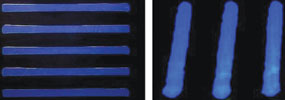
Automatic inspection of the coated area can quickly be completed by utilising the active vision system on the coating machine. By creating contrast to the board surface, often fluorescing the coating under black light, the camera can take an image of a coated area and compare to a master image that has been designated as an acceptable pattern. Image sensitivity can be altered to match the desired tolerance level. The captured image will layer over the master image to determine acceptability.
Similar to the flow monitor option, inspection provides a snapshot of only one variable. In the case of the coating position, though, no feedback on the actual volume is provided. This is why the camera and flow monitoring options are often used in tandem to provide feedback on both parameters.
| Tel: | +27 11 609 1244 |
| Email: | [email protected] |
| www: | www.zetech.co.za |
| Articles: | More information and articles about ZETECH ONE |


© Technews Publishing (Pty) Ltd | All Rights Reserved
 printer friendly version