


Ensuring functional correctness on RTL designs continues to pose one of the greatest challenges for today’s FPGA and ASIC design teams. Very few project managers would disagree with this statement. In fact, an often cited 2004 industry study by Collett International Research revealed that 35% of the total ASIC development effort was spent in verification[1]. In 2007, a Far West Research study indicated the verification effort has risen to 46% of the total ASIC development effort[2].
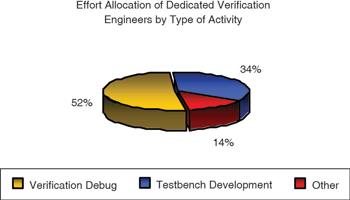
Furthermore, these industry studies reveal that debugging is the fastest growing component of verification, and that it consumes 52% of the total verification effort.
Unfortunately, with the increase in verification effort, the industry has not experienced a measurable increase in quality of results. For example, the Far West Research study indicated that only 28% of projects developing ASICs were able to achieve first silicon success. To make matters worse, the industry is witnessing increasing pressure to shorten the overall project development cycle. Clearly, new design and verification techniques, combined with a focus on maturing functional verification process capabilities within an organisation (and the industry as a whole) are required.
Today we are witnessing a phenomenal increase in FPGA design starts as one means to reduce risk. In fact, Gartner in 2009 reported that FPGAs had a 30-to-1 edge over ASICs in design starts. Although FPGAs have traditionally been relegated to glue logic, low-volume production or prototype parts used for analysis, this is no longer the case. Gate count and advanced features found in today’s FPGAs have increased dramatically to compete with capabilities traditionally offered by ASICs alone.
The change in FPGA capabilities has resulted in the emergence of advanced FPGA system-on-chip (SoC) solutions, which includes the integration of third-party IP, DSPs and multiple microprocessors – all connected through advanced, high-speed bus protocols. Accompanying these changes has been an increase in design and verification complexity, which traditional FPGA flows are generally not prepared to address.
This article considers an easy technique for addressing verification complexity by evolving an organisation’s simulation process capabilities – specifically through the adoption of assertion-based verification (ABV).
What is an assertion?
Informally, an assertion is a statement of design intent that can be used to specify design behaviour. Assertions may specify internal design implementation features, eg, some aspect of a specific FIFO structure. Alternatively assertions may specify external architectural (or micro-architectural) features, for example a bus protocol or even higher-level, end-to-end behaviour that spans multiple design blocks.
One key characteristic of assertions is that they allow us to specify what the design is supposed to do at a high level of abstraction, without having to describe the details of how the design was implemented. Thus, this abstract view of the design intent is ideal for the verification process – whether we are specifying high-level requirements or lower-level implementation behaviours – by means of assertions.
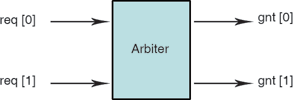
Let us examine a simple implementation assertion. For this example we use a simple two-client arbiter, as illustrated in Figure 1. A requirement of our simple two-client arbiter is that the grants remain mutually exclusive to prevent resource conflicts when accessing a shared resource. In other words, for our specific example, the arbiter should never assert gnt[0] and gnt[1] at the same time. We can specify this requirement using a SystemVerilog assertion, as demonstrated in Figure 2.
Does this stuff really work?
The benefit of having this particular assertion present during the course of simulation is that if there is a bug in our arbiter implementation, which caused two grants to be asserted at the same time, then our assertion would trigger. Thus, any improper or unexpected behaviour can be caught closer to the source of the design error, in terms of both time and location. Hence, the use of assertions dramatically reduces our debugging effort.
When asked what the biggest bottleneck in their verification flows is, the Far West Research participants responded that debugging was their issue, as illustrated in Figure 3. Hence, anything that can be done to reduce the debugging effort is a huge win for the overall project schedule.
Assertions significantly reduced debugging time, as measured and described in the following case studies:
* 50% reduction in simulation debugging time published by IBM.[3]
* 50% reduction in simulation debugging and 85% reduction in formal debugging time published by Sun Microsystems.[4]
From these case studies, a common theme emerges: when design and verification engineers use assertions as a part of the methodology, they are able to detect a significant percentage of design failures while reducing debugging time as a result of improved observability.
Controllability and observability
Fundamental to the discussion of assertion-based verification is understanding the concepts of controllability and observability[5].
Informally, controllability refers to the ability to influence or activate a specific line of code within the design by stimulating various input ports. Note that, while in theory a simulation test bench has high controllability of the design model’s input ports during verification, it can have very low controllability of an internal structure within the model.
Observability, in contrast, refers to the ability to observe the effects of a specific stimulated line of code. Thus, a test bench generally has limited observability if it only observes the external ports of the design model (because the internal signals and structures are often indirectly hidden from the test bench).
To identify a design error using a simulation test bench approach, the following conditions must hold:
1. The test bench must generate proper input stimulus to activate a design error.
2. The test bench must generate proper input stimulus to propagate all effects resulting from the design error to an output port.
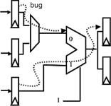
It is possible, however, to set up a condition where the input stimulus activates a design error that does not propagate to an observable output port, as illustrated in Figure 4.
Embedding assertions in the design model increases observability. In this way, the test bench no longer depends on generating input stimulus to propagate a design error to an observable port. In fact, one observation made by teams just getting started with ABV is that, after the assertions are enabled, their simulations that had previously been working often fail as new bugs are identified due to improved observability, thus resulting in an overall
reduction of debugging time.
While embedded assertions help solve the observability challenge in simulation, they do not help with the controllability challenge. However, the existence of assertions within the flow does open up the possibility for utilising formal property checking to target critical or high-value assertions, thus addressing the controllability challenge.
Who should write the assertions?
A question I often hear by engineers just getting started with ABV is “who should write the assertions?” Assertions added at any level of hierarchy clearly benefit verification by reducing debugging time while clarifying design intent. Certainly, multiple stakeholders within the design and verification process can contribute to the assertion development process, thus reducing ambiguities while improving observability.
Figure 5 illustrates a typical design refinement process through various levels of abstraction and the stakeholders associated with each level. Adoption of assertions in the industry, at the time of this writing, has predominately occurred within the block and module level. They can be called implementation assertions. This adoption trend is partially due to the lack of effective guidelines for assertion use at higher levels of design hierarchy (or abstraction) and confusion about which stakeholders should contribute to the assertion development process.
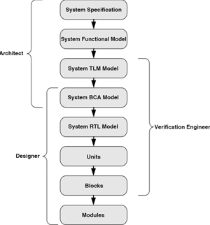
Although an architect can contribute to the assertion development effort by defining global properties (derived from the architecture and micro-architectural specification) that must hold across multiple possible implementations, the design engineer contributes by writing internal white-box assertions derived from the implementation. In addition, the verification engineer contributes by developing assertions that specify correct interface behaviour between units and between blocks. The verification engineer also contributes by developing black-box, end-to-end assertions across design components.
From a verification planning perspective, the verification engineer generally does not track any of the low-level implementation assertions added to the RTL by the design engineer. These low-level assertions are analogous to checking that a pointer is not NULL before it is used in a software program. They are invaluable at isolating problems, and you will be very glad they are there when a problem occurs, yet these assertions do not map back to any requirements defined in the architectural or micro-architectural specification.
For mature design teams who have applied an ABV methodology on multiple projects, there will typically be tens of thousands of these low-level assertions for larger designs (for example, more than 10 million gates).
The verification engineer is generally concerned with assertions above the RTL implementation – that is, architectural and micro-architectural assertions. Examples of these types of assertions include block-level interfaces and bus protocols, as well as multiblock end-to-end assertions. Unlike low-level implementation assertions, these higher-level assertions are often defined and tracked as part of the verification planning process.
Getting started with ABV
There are two industry assertions language standards available today:
* An assertion language embedded in the IEEE 1800-2005 SystemVerilog standard know as SVA.
* The IEEE 1850-2005 Property Specification Language (PSL).
In addition, there is an assertion library standard from Accellera known as the Open Verification Library (OVL)[6], which is available in Verilog, VHDL, SystemVerilog and PSL.
From the perspective of an FPGA or ASIC designer who is just getting started with assertions, the OVL provides a simple learning curve for adoption. The designer can instantiate one of the Verilog or VHDL OVL checkers directly into their RTL design without having to learn an assertion language. In fact, what we see today is that often these low-level implementation assertions are just simple Boolean checks, which do not require the full power of either PSL or SVA.
From a verification engineer’s perspective, PSL or SVA serves their needs better due to the expressiveness of these languages. These engineers are focused on writing higher-level assertions, such as bus protocols or end-to-end assertions involving multiple blocks.
To learn more about ABV and how to evolve your organisation’s verification process capabilities, readers can visit the Verification Academy website at www.verificationacademy.com.
References
[1] R. Collett, ‘2004 IC/ASIC functional verification study’, industry report from Collett International Research, p.34, (2004).
[2] FarWest Research 2007 industry study in conjunction with Mentor Graphics.
[3] Y. Abarbanel, I. Beer, L. Gluhovsky, S. Keidar, Y. Wolfsthal, ‘FoCs—Automatic Generation of Simulation Checkers from Formal Specifications’, Proc. 12th International Conference Computer Aided Verification, pp. 414-427 (2000).
[4] B. Turumella, M. Sharma, ‘Assertion-based verification of a 32 thread SPARC CMT microprocessor’, in Proceedings of the 45th Design Automation Conference, DAC 2008, pp. 256–261, (2008).
[5] E. Marschner, H. Foster, ‘Assertion-Based Verification’, EDA for IC System Design, Verification, and Testing (Electronic Design Automation for Integrated Circuits Handbook), edited by L. Scheffer, L. Lavagno, G. Martin, CRC Press, pp. 18-1..18-12 (2006).
[6] Accellera Standard OVL Library Reference Manual, www.accellera.org (2008).
| Tel: | +27 11 315 8316 |
| Email: | [email protected] |
| www: | www.asic.co.za |
| Articles: | More information and articles about ASIC Design Services |


© Technews Publishing (Pty) Ltd | All Rights Reserved
 printer friendly version