


Like all RF and microwave components, a differential filter design will remain only a simulation exercise if it is not created with its manufacturing process in mind. That is, the tight dimensional tolerances required to meet a set of performance goals must be within the capabilities of the filter’s manufacturing process in order to realise a reliable, repeatable filter.
Geometries that are difficult to manufacture, such as very wide lines with very narrow gaps or very narrow lines with very wide gaps, are typically accompanied by extreme resonator impedance swings.
A filter synthesis tool must be able to automatically manage these impedances using analytical and empirical techniques (such as Norton and Kuroda transforms, and m-derived and constant-k end sections) to mitigate extreme impedances and produce geometries that can be easily realised. A hairpin bandpass filter with a target centre frequency of 5,8 GHz will be used in this article as an example to illustrate how this can be accomplished using AWR’s Microwave Office software with iFilter technology to synthesise the structure, and then AWR’s AXIEM 3D planar electromagnetic (EM) solver to validate it.
The target design
The design target is a bandpass filter with a centre frequency of 5,8 GHz, 3 dB bandwidth of 200 MHz, passband insertion loss of less than 2 dB, passband return loss of more than 15 dB, and stopband insertion loss of more than 40 dB at 5,4 GHz and 6,2 GHz. It will be fabricated using Rogers RT/duriod RO 6006 that is 0,01” thick, uses 1-oz. copper and has a dielectric constant of 6,15.
It must be realisable using the most simple manufacturing process possible, in which there are only printed structures and no via holes or external components.
The filter’s fractional bandwidth is:
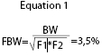
where FBW = fractional bandwidth, BW = bandwidth, F1 = lower 3 dB frequency and F2 = upper 3 dB frequency.
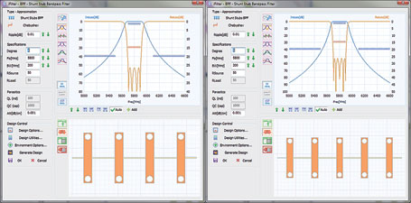
Common topologies such as edge-coupled structures create difficulties when fractional bandwidth (FBW) is less than about 15%. An edge-coupled filter with such a narrow bandwidth would synthesise with narrow lines and wide gaps that are much larger than the line widths, which translate poorly into physical designs. Consequently, alternative topologies such as a shunt stub must be considered. Figure 1, a shunt-stub topology, shows that four poles are insufficient to meet the rejection requirement while five poles provide a satisfactory amount of rejection.
Before going further, it is important to determine which filter topology is most manufacturable. The options include shunt-stub, edge-coupled, hairpin, interdigital, combline and stepped-impedance resonator types. The iFilter software enables users to superimpose on each other the various topologies that meet the filter’s specifications and evaluate them in terms of footprint and manufacturability.
This comparison is shown in Figure 2 for three different options: shunt stubs with quarter-wave lines and quarter-wave stubs (orange), edge coupled (lighter blue) and hairpin (darker blue). Using this as a guide and keeping in mind the goal of using the least expensive manufacturing process, the hairpin design is chosen because it has a much smaller footprint, is designed to keep line widths constant for easy manufacturing, and the entire filter is printed without the need for via holes or external components.
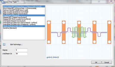
The footprint could be reduced by selecting an interdigital or combline configuration, but both of these topologies include extra manufacturing steps, such as via holes for interdigital filters and vias and surface-mounted capacitors at the ends of the resonators for combline filters. This is not an acceptable solution, as its slightly smaller footprint is not justified by its increased manufacturing costs.
Limits of 0,004” for minimum line width and minimum line spacing are specified in iFilter – which are typical dimensions for modern printed circuit board processes. iFilter will notify the user if the design violates those limits, as shown in the red-outlined boxes in Figure 1. (Note: At this stage of the design, the hairpin topology has not yet been selected and thus the filter type shown within Figure 2 violated at least one of these requirements.)
The main iFilter window is set up to produce the desired filter, the electrical requirements are specified, the hairpin topology is selected, and the substrate information is entered in the ‘Design Options’ window (Figure 3).
iFilter also provides the ability to adjust secondary parameters in real time and see the results which, in the case of hairpin filters, includes adjustment of the filter’s nominal impedance. The short connecting lines between the resonators (in the U-turns), will have this impedance and the resonator lines will share this linewidth. If the area is assumed to be limitedto 0,36 x 0,30 inches, the nominal impedance of the resonators can be adjusted to examine the effects of line width on performance and required area (Figure 4).
Based on the filter’s footprint, the Zo = 55 Ohms version for the synthesis will be used. At this point, iFilter’s work is almost done and the results are ready to be passed over to Microwave Office for the remaining design tasks. The filter’s specifications have been set up as optimisation goals (visible in all graphics that include the response graph) and will be added to the project. The design in Microwave Office can be set up with a simple button click that produces the project shown in Figure 5.
The Microwave Office filter project was created with all critical parameters set to be tuned and optimised. With iFilter, the analysis can be run automatically after creating the project, so the screen shown in Figure 5 is exactly what is seen after sending the filter to Microwave Office.
Moving to AXIEM
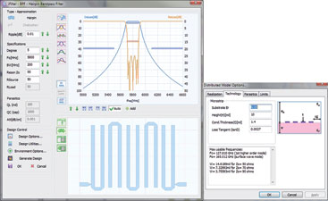
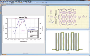
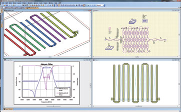
The filter’s passband is very close to the desired result and the stopband requirements are nearly met, but there is little margin on the low side and the return loss must be increased. The next step is linear optimisation, followed by EM analysis and further EM optimisation, if desired. In this distributed hairpin bandpass filter, the Simplex linear optimiser was run for 100 iterations and the resulting filter was analysed with AXIEM (AWR’s 3D planar electro-magnetic simulation software) to produce the response and filter performance shown in Figure 6.
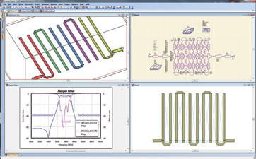
The final step in the design process is to further optimise the filter via more EM analysis within the AWR extraction flow utilising AXIEM. The extraction flow permits the design to be optimised at the schematic level using the EM engine to perform the analysis for each iteration of the optimiser. It also enables the automatic generation of a new EM structure every time the geometry changes based on the optimiser’s guidance. The EM optimisation approach in this case employed AXIEM’s advanced frequency sweep option and each iteration took less than 20 seconds.
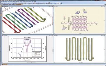
Now nearly all of the goals originally set for this example have been achieved, as shown in Figure 7. Passband insertion loss is reasonable, stopband insertion loss is very low, and there is some margin available to accommodate manufacturing tolerances. Only return loss is too low over a small portion of the band. And while there are many options the designer can choose for increasing return loss, such as changing the tap location, shortening the first and last lines slightly, or both, these final variations are beyond the scope of this article.
Conclusion
Filtering is becoming ever more important in wireless network deployments at frequencies also occupied by other services, for IEEE 802.11n WiFi in the 5 GHz band, and in the upcoming services that will operate in the new 700 MHz allocations, among others. Consequently, in order to reduce the potential for interference, the ability to rapidly and accurately produce filters with high levels of rejection and other desirable characteristics is critical.
Filter synthesis tools such as AWR’s iFilter software were specifically developed to enable designers to quickly and easily create filters that incorporate features to ensure they conform to specific manufacturing constraints and costs. While a distributed-element filter was used in this application example, iFilter is equally adept at handling lumped-element designs as well.
For more information contact DS Communications, +27 (0)11 314 4101, [email protected], www.dscoms.com
| Tel: | +27 11 314 4101 |
| Email: | [email protected] |
| www: | www.dscoms.com |
| Articles: | More information and articles about DS Communications |


© Technews Publishing (Pty) Ltd | All Rights Reserved
 printer friendly version