


Equipment design involving strain gauges, transducer interfaces and current monitoring for technologies such as medical equipment, automotive instrumentation and industrial control often requires a precision analog front-end amplifier that is able to extract and amplify a very small real-world signal, while rejecting unwanted signals such as common-mode voltages and noise.
To begin with, the designer will focus on ensuring that accuracy parameters such as component-level noise, offset, gain and temperature stability are suitable for the application.
Based on these specifications, the designer chooses front-end analog components that will fit the permitted total error budget. However, an often overlooked problem occurs in such applications, caused by high-frequency interference from external signals. It is typically categorised as electromagnetic interference (EMI).
Principally affected by the end application, EMI can occur in numerous ways. For example, an instrumentation amplifier might be used in a control board that interfaces with a DC motor. The electrical current loop of the motor, which comprises power leads, brushes, commutator and wire coil, can often act as an antenna that emits high-frequency signals that can interfere with the small voltages at the inputs of the instrumentation amplifier.
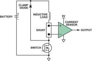
Another example is current sensing in automotive solenoid control. The power to the solenoid is provided by the vehicle battery via long wires that can act as antennas. A series resistive shunt is connected in this wire path, with its voltage measured by a current sensing amplifier. The inputs of the amplifier are susceptible to external high-frequency common-mode signals that could be present in the wiring.
If the analog component is affected by external high-frequency interference, it may lose accuracy and could perhaps even lose control of the solenoid circuit. This condition would be manifested in the amplifier by its output accuracy exceeding the error budget and data sheet tolerance, or in some cases going into limits, causing shutdown of the control loop.
How can EMI cause large DC deviations? Here is one possible mechanism: Many instrumentation amplifiers are designed and specified to have excellent common-mode rejection at frequencies well up into the tens of kilohertz. The problem comes in exposure of an unshielded amplifier to RF fields in the tens or hundreds of megahertz. Asymmetrical rectification can occur in the input stages of the amplifier, producing DC offsets that, further amplified, can be significant and – considering the gain of the amplifier – even drive its output, or some portion of the external circuit, into limits.
Example of how an analog component is affected by high-frequency signals
This example will take a closer look at a typical high-side current sense application. A common configuration for monitoring solenoids or other inductive loads in an automotive environment is shown in Figure 1.
The effects of high-frequency interference in such a setup were investigated with two current sense amplifiers of similar design. The functionality and pinout of the two parts were exactly the same; however, one device included internal EMI filter circuitry, while the other did not.
Figure 2 shows how the DC output of the current sensor varied from its ideal value as the inputs were subjected to a wide range of frequencies. It can be seen that significant deviations (>0,1 V) occur in the frequency range of 1 MHz to 20 MHz, with a peak DC error of 1 V – a significant portion of the amplifier’s 0–5 V range – at 3 MHz.
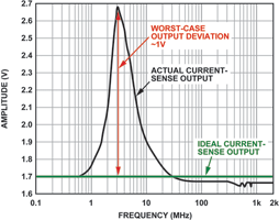
Figure 3 shows the results of the same experiment and setup using a pin-compatible current sensor that has the same circuit architecture and similar DC specifications as in the previous case, but it includes internal input EMI filtering. Note that the voltage scale is expanded by 20 times.
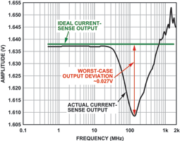
In this case, the error level is only about 3 mV at 40 MHz, and the peak error, at above 100 MHz, is less than 30 mV, a greater than 35x improvement. This shows quite clearly that internal EMI filtering helped a great deal to shield the current sensor from the high-frequency signals present at its inputs. In a real-world application, where the extent of EMI is unknown, it can be realistically expected that the control loop will remain within its tolerance if the current sensor with internal EMI filtering is used.
The testing was done under the exact same conditions for both parts. The only difference between them is that the AD8208 includes internal low-pass RF input filters on the input and power supply terminals. This might seem like a trivial addition to the silicon, but in this case the current sense amplifier must withstand continuously switching common-mode voltages up to 45 V, as the applications are typically PWM controlled. Therefore, to maintain accurate high gain and common-mode rejection, the input filters must be closely matched.
Why and how to design and test for EMI compliance
Automotive applications are particularly sensitive to EMI events due to the noisy electrical environment associated with the common battery, bundled wiring, various inductive loads, antennas and outside interference associated with cars. Because electronics is involved in controlling critical functions, including airbag deployment, cruise control, braking and suspension, EMI compliance is a must. There can be no false alarms or triggers due to external interference.
In earlier times, EMI compliance testing was the last test performed in automotive applications. If something went wrong, designers had to scramble to find a solution – which typically involved changing the board layout, adding additional filters or even replacing components.
This level of uncertainty is costly and worrisome for engineers, and over time the automotive industry has taken concrete steps to improve EMI compliance. Automotive OEMs, whose equipment must be EMI compliant, now demand EMI testing at the component level from semiconductor manufacturers prior to qualifying a part for use. This process is becoming universal, as all IC manufacturers are now instructed to test components for EMI compliance using a standard specification.
Requirements for standard EMI tests for various types of integrated circuits can be purchased from the International Electrotechnical Commission (IEC). Documents such as IEC 62132 and IEC 61967 are very good tools to learn about EMI and EMC; they describe – in great detail – how to test specific integrated circuits using industry-recognised standards. The tests described above were performed using these specified guidelines.
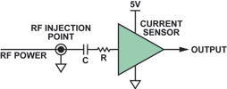
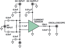
In particular, these tests were done using direct power injection, a method that couples an RF signal, via a capacitor, to a particular component pin. Each input of the device is tested, varying the power level and frequency range of the RF signal, depending on the type of IC under test. Figure 4 depicts a simplified schematic of how direct power injection testing is conducted at a particular pin.
The standards include quite a bit of information on the circuit setup, layout methods and monitoring techniques necessary to understand whether a part passed or failed. A more complete schematic based on the IEC specifications is shown in Figure 5.
| Tel: | +27 11 923 9600 |
| Email: | [email protected] |
| www: | www.altronarrow.com |
| Articles: | More information and articles about Altron Arrow |


© Technews Publishing (Pty) Ltd | All Rights Reserved
 printer friendly version