


Aldec’s Active-HDL is a Windows-based, integrated FPGA design creation and simulation solution for team-based environments. The tool’s integrated design environment (IDE) includes a full HDL and graphical design tool suite and RTL/gate-level mixed-language simulator for rapid deployment and verification of FPGA designs.
The design flow manager evokes 120+ EDA and FPGA tools during design entry, simulation, synthesis and implementation flows, and allows teams to remain within one common platform during the entire FPGA development process.
Active-HDL supports industry leading FPGA devices from Altera, Atmel, Lattice, Microsemi (Actel), Quicklogic, Xilinx and others.
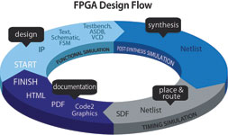
A typical FPGA design flow includes the design entry phase, synthesis and implementation (fitting and Place & Route processing), each stage typically followed by simulation. The configurable Design Flow Manager interfaces with the vendor tools and allows a designer to remain on one platform throughout the FPGA development. In a team environment, the design flow settings can be applied and enforced on every team member.
ActiveHDL allows designs to be captured quickly by using text, schematic and state machine editors.
The HDL text editor is tightly integrated with the compiler and simulator to assist with debugging; for example, cross-probing between the text editor and waveform viewer, adding live value probes in source code during simulation.
Other features of HDL text editor are keyword highlighting, support for code groups and code structure, auto-complete and auto-format, and bookmark for easy navigation through source code. Language templates for VHDL, Verilog, SystemVerilog and SystemC help with the code creation process.
The block diagram editor is a tool for graphical entry of VHDL, Verilog and EDIF designs.
If an HDL design is in large part structural, it may be easier to enter its description graphically as a block diagram (schematic), rather than writing the source code. The block diagram editor will then convert the diagram automatically into structural VHDL, Verilog or EDIF netlist.
For example, the top-level design entity can be a block diagram while the components instantiated in it are described using HDL code, state diagrams and/or more block diagrams. The block diagram editor supports both bottom-up and top-down methodologies.
The state diagram editor is a tool designed for the graphical editing of state diagrams of synchronous and asynchronous machines. Drawing a state diagram is an alternative approach to the modelling of a sequential device – a graphical view of a state machine is generally easier to read than numerous pages of HDL code.
Instead of writing the HDL code, users can enter the description of a logic block as a graphical state diagram. The editor will then automatically generate the HDL code based on the entered graphical description. The code generation can be customised to conform to personal or corporate coding standards.
Simulation is achieved by a powerful common kernel mixed language simulator that supports VHDL, Verilog, SystemVerilog and SystemC.
ActiveHDL has extensive support for VHDL-2008. VHDL-2008 adds important language enhancements for verification and delivers many benefits from numerous added functionalities, including PSL incorporation (properties and assertions support), IP protection (encrypted files compilation), VHPI, fixed and floating-point packages, generics packages, new types (integer_vector and boolean_vector, etc.), process for combinatorial logic, simplified conditional and case statements, extended assignments, new and enhanced operators, extended bit string literals, enhanced port maps, context declarations and clauses.
The verification quality is improved by making use of Code Coverage analysis tools and other techniques such as assertion-based verification (SVA, PSL, OVA). Furthermore, the gap between HDL simulation and high-level mathematical modelling environment for DSP blocks using MATLAB/Simulink is bridged by a plug-in interface.
A built-in documentation tool inside Active-HDL allows users to create a textual and graphical representation of their workspace or design in HTML or PDF. All design elements such as design files, waveforms, block diagrams and attached documents can be exported to HTML or PDF documents.
This is helpful for tasks such as design reviews, reuse and archiving. The resulting documents always preserve the hierarchy of the design, with navigation within designs made possible using hyperlinks.
| Email: | [email protected] |
| www: | www.logiclab.co.za |
| Articles: | More information and articles about Logic Lab |


© Technews Publishing (Pty) Ltd | All Rights Reserved
 printer friendly version