


Programs for simulation of electronic circuits have been used for some time. The best known is the Spice simulator developed in the mid-1970s, now available worldwide in many variants. Spice software uses mathematical models for a wide range of components. It calculates and tests the desired circuit function from simulation data compiled by the designer, then outputs the results in an easy-to-interpret form. Resulting benefits, such as high operational reliability and fewer test circuits, cut development time and costs. Working in a Microsoft Windows environment, designers can generate a simulated circuit in the usual way, by inputting a circuit diagram of components from one of the extensive libraries now available.
The PSpice Simulator from OrCAD is one of the most popular program packages for circuit simulation. The varistor model for PSpice is described by four parameters, which designers can access in the model library with the PSpice model editor.
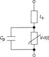
To create a model with PSpice, the varistor is replaced by a current-voltage characteristic, a parallel capacitance, and a series inductance (Figure 1). The current-voltage characteristic is simulated by a controlled voltage source V, which is a function of current I. An additional series resistance R2 of 100 µOhm, which is not visible in the basic configuration, is inserted into the model. The current-voltage characteristic prevents invalid conditions from arising as a result of connection of ideal sources in parallel or direct connection of the varistor model to a source. This can be described mathematically by the following approximation:
log V = b1 + b2 x log(I) + b3 x e-log(I) + b4 x log(I) when I > 0
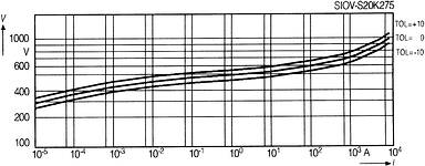
The characteristic for a particular varistor can therefore be described by parameters b1 to b4. The typical V/I characteristic for the varistor we used for modelling (SIOV-S20K275) and its associated parameters are shown in Figure 2. The characteristic can move within its tolerance range defined by the specified varistor voltage. The standard tolerance for varistors is 10%. The tolerance range can be simulated with the parameter TOL by shifting the mean varistor characteristic. The typical characteristic (middle curve) is obtained when TOL is zero. The upper curve relates to a varistor voltage tolerance of +10% (TOL = 10) and corresponds to the curve shown in the manufacturer's data book for the maximum protection level. The lower curve relates to a tolerance of 10% (TOL = 10) and corresponds to the curve shown in the data book for maximum leakage current at currents up to 1 mA.
The typical capacitance given in the manufacturer's data book is inserted into the model. We ignored the slight variation of capacitance with the voltage applied and frequency for this study. The inductance of the varistor, on the other hand, must not be ignored in applications with steep pulse edges. It is therefore covered by a series inductance and largely determined by the inductance in the leads attached to the ceramic disk. In contrast, the internal inductance of the zinc oxide varistor can be ignored. The inductance values covered in the model library apply to typical varistor mountings. An inductance of about 13 nH is obtained for the varistor studied. Longer varistor leads can be modelled by inserting additional inductances into the simulation circuit. The specific inductance of the leads of disk varistors is about 1 nH per millimetre.
The limits of modelling
For mathematical reasons, the V/I characteristic is extended in both directions beyond the current range (10 µA to Imax) specified in the data book and is not limited by PSpice. If the simulation exceeds these limits, the model loses validity. Values of less than 10 µA can therefore lead to incorrect simulation results, but do not endanger the real component. Moreover, exact knowledge of leakage currents in the range of up to 10 µA is only required in exceptional cases for varistor applications. But confidence in values above the type-specific surge current Imax can lead to destruction of the real component as well as falsification of the result. What is more, the varistor model does not check compliance with other limit values, such as maximum continuous power or pulse derating. Therefore this compliance must always be verified against the figures in the data book as well as by simulation.
Zinc oxide varistors have a negative temperature coefficient of voltage. This coefficient, TK, is equal to 0,05% K and decreases as current density increases. However, this relationship is not reproduced in the model because it has negligible influence on the protection level of the varistor.
Pulse test simulation
A test pulse of 10/700 µs duration as specified by CCITT or IEC 1000-4-5 is often used to check interference immunity of telecommunications equipment. The test pulse is defined by the test generator circuit and the given open-circuit voltage. For an open-circuit voltage of 2 kV, the charging capacitor must be charged up to 2,05 kV. An additional resistance R1 of 10 MOhm is inserted at the output to prevent undefined floating of the series resistor (Rm2).
For worst-case simulation, ie the maximum protection level, the tolerance of the upper characteristic (TOL = 10) is used for this varistor. There is no need to simulate the equipment to be protected because it can be regarded as high impedance with respect to the varistor when the test pulse is applied. The curves calculated (Figure 3) show that the varistor can reduce the interference voltage at the equipment connected to 2 kV to less than 260 V.
The derating field for the varistor studied (Figure 4) shows that with this value and at the maximum current Imax, 10 pulse loads can be applied.
In conjunction with the varistor's maximum continuous power-handling capacity, Pmax, of 0,4 W, the minimum pulse interval, Tmin, can be determined as follows: Tmin = W/Pmax = 4,2 J/0,4 W = 10,5 s.
Since 10 pulses with a duration of 10/700 µs applied at one-minute intervals are specified for telecommunications equipment, the varistor studied is suitable for this application.
Whether the varistor's operating voltage of 95 Vrms is suitable for the application depends on the protection level required for the equipment as well as the operating voltage (eg DC supply voltage, ringing tone voltage). If required, lower protection levels can be obtained by using a lower operating voltage or a larger-diameter varistor. However, designers should always make sure that the maximum operating voltage is equal to or less than the maximum operating voltage of the varistor.
| Tel: | +27 11 458 9000 |
| Email: | [email protected] |
| www: | www.electrocomp.co.za |
| Articles: | More information and articles about Electrocomp |


© Technews Publishing (Pty) Ltd | All Rights Reserved
 printer friendly version