


Digital signal processing (DSP) and communications engineers are turning to digital filters for applications with power and size constraints that affect their filter design.
Achieving an optimal filter design requires careful analysis and selection of the most accurate filters. The Filter Design and Analysis Tool (FDATool) is the new interface to the Signal Processing Toolbox and the Filter Design Toolbox from The MathWorks. It provides easy and accurate access to the advanced methodology for this optimal filter design. Here, we will focus on the filtering techniques used in software-defined radio (SDR), an emerging technology in which digital filters are critical components
Software-defined radio
Software-defined radio technology is increasingly being used in a wide range of wireless applications. It has been gaining popularity in the wireless communications industry since the advent of powerful DSPs (digital signal processors). In the transmitter, the baseband signal is generated using programmable digital signal processing techniques. Then the signal passes through pulse shaping filters to limit the transmitted bandwidth. Finally, it is up-converted to IF (intermediate frequency) using a NCO (numerically controlled oscillator), which allows for channelisation by simply manipulating its control word (typically 32 bits). The final stage is the IF-to-RF, which is typically implemented in the analog domain.
In the receiver, the RF (radio frequency) signal is downconverted to IF and then sampled and processed using programmable digital signal processing techniques. Because sampling takes place closer to the antenna, this technology allows for the implementation of multiple standards on a single hardware platform. For example, by reconfiguring the software for a TDMA-GSM-based phone we can make it support other standards, such as CDMA-95A.
In addition to its software programmability, SDR technology enables wireless modem manufacturers to achieve economy of scale. This is because SDR-based modems exploit undersampling to eliminate the use of common analog components, which are costly and unreliable. For example, using a single analog-to-digital converter to sample the IF signals eliminates the need for analog IF-to-baseband down-conversion, hence avoiding the use of analog mixers and low pass filters.
Filtering methods in SDR
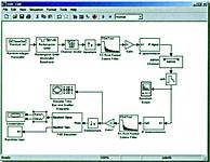
At the heart of any wireless modem design is the use of transmitter and receiver pulse shaping filters. The Nyquist criterion states that in order to have zero intersymbol interference (ISI) at the optimum sampling instant, the cascaded impulse response of these two filters must have zero crossings at the symbol rate. A commonly used pulse-shaping filter is the 'raised cosine filter'. By controlling the roll-off factor b, the design can be optimised for less bandwidth (b closer to 0) or for less ISI (b closer to 1). A value of 0,35 is commonly used in 2G cellular applications. For bandwidth efficiency, a value of 0,22 for b is used for 3G cellular applications, making timing recovery a challenging task. Therefore, it becomes important to find the best filter coefficients for a particular implementation. The basic signal processing chains for the transmitter and receiver sections of a software-defined radio are shown in Figure 1. There are several methods commonly used to perform signal interpolation. For simplicity, we'll use up-sampling (zero insertion) followed by a lowpass filter. In this example, the lowpass filter is chosen to have a root raised cosine shape so that one filter performs both matched filtering and the suppression of (spectral) images introduced by up-sampling (see Figure 1).
Filter Design and Analysis Tool
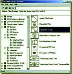
The Filter Design and Analysis Tool was recently integrated with Simulink, and enables one to try different filters very quickly and accurately. As seen in Figure 2, FDATool is represented as a Simulink Block in the DSP Blockset.
Once the FDATool block is placed in the Simulink model, double-clicking on it will launch the GUI as the block parameters. Here one can select the filter specifications for one's design. In this example, the root raised cosine filter is chosen where the standard stopband attenuation is -40 dB and the sampling rate is Fs = 40 MHz (5 MHz, the symbol rate, multiplied by the upsampling factor of 8). Theoretically, a 5 MSymbol/s (in this case QPSK symbols) signal can be transmitted using only 2,5 MHz bandwidth but at the expense of severe ISI. So Fc = 2,5 MHz and the excess bandwidth in this case is controlled by the roll-off factor [in our example the total transmitted bandwidth is (1+0,35) x 2,5 = 3375 MHz]. Once these parameters have been set, the response of the filter is generated instantly.
Results
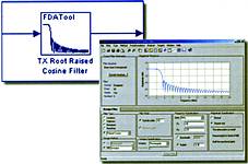
It is easy to go back and make changes to the filter design by experimenting with the filter order and the windowing method until the most desirable response is obtained. In addition to the magnitude response, one can view the phase response, filter coefficients, step and impulse responses, as well as the pole/zero plot. (See Figure 3.)
This is one example of the advanced filtering methods accessible with the Filter Design and Analysis Tool. The FDATool GUI ships with the Signal Processing Toolbox and is available as a block in the DSP Blockset. FDATool seamlessly integrates additional functionality from other MathWorks products, such as the Filter Design Toolbox, which provides advanced filter design and quantisation, and the Developer's Kit for Texas Instruments DSP, which allows users to download their filter to Texas Instruments boards.
For further information, contact The MathWorks local representative, Opti-Num Solutions, 011 325 6238.
| Tel: | +27 11 325 6238 |
| Email: | [email protected] |
| www: | www.optinum.co.za |
| Articles: | More information and articles about Opti-Num Solutions |


© Technews Publishing (Pty) Ltd | All Rights Reserved
 printer friendly version