


Power supplies can be found in almost any circuit. From radio transceivers to microprocessors, FPGAs and amplifiers, it’s a guarantee that a power supply block exists somewhere, which makes one a vital part of any analog or digital circuit.
Like any other component, power supplies come in many shapes and forms. Different architectures, such as linear regulators or switching mode regulators, present advantages and disadvantages, making one beneficial over the other in certain applications. In all these architectures, one common denominator is that the output is usually dictated by a combination of external parts, especially feedback resistors.
With the help of simulation tools, a power supply can be designed to fit the necessary specifications and come up with component values that meet them. Although simulation results show promise, limitations exist in real-life settings. One common example would be component tolerance. In reality, the rated values of components such as resistors or capacitors vary and this variance is what tolerance describes. A simulated combination of 57 kΩ and 23 kΩ resistors to output a 5 V signal would be different from a real-life combination of 57 kΩ and 23 kΩ since the components will vary. This tolerance affects the accuracy of the DC output voltage as well, aside from inherent errors to the IC.
Regulator output calculation
Many Analog Devices voltage regulator ICs have an output feedback pin (FB or ADJ pin). Thus, the output voltage can be set with a pair of external resistors, RTOP and RBOT, where RTOP connects to the VOUT and FB pin, and RBOT connects the FB pin and IC signal ground pin. Usually, the standard IC data sheet equation is given as (see Equation 1):

Where VREF is the IC internal reference voltage as an internal input of the feedback error amplifier. Let’s take the output voltage formula for the LT3062 linear regulator as an example. Figure 1 shows its computed output voltage.
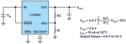
With an internally generated and assumed to be accurate, voltage reference (VREF = 0,6 V of the LT3062) the output voltage divider feedback network (R1 and R2) dictates the voltage level that the IC regulates. In the LT3062 equation, there is an additional term from IADJ: the unintended bias current flowing out from the ADJ pin. Its typical value is 15 nA, but can be as high as 60 nA, as shown in the electrical characteristics (EC) table and it can cause additional VOUT regulation error.
If 1% tolerance R1 and R2 resistors are used, what is the total voltage error caused by the resistor divider – 1% or 2%? Should we use 0,5% or 0,1% resistors for an application? Certain levels of accuracy in the output voltage might be needed and choosing the right resistors plays a key role. You may not want to use resistors that have very low tolerance (which can be significantly expensive) if the target error can be reached with a higher-tolerance resistor.
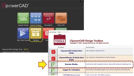
LTpowerCAD resistor divider tool
To aid in the design, the LTpowerCAD resistor divider tool can be used. LTpowerCAD is a complete power supply design program equipped with a toolbox of design assets including the resistor divider design tool. The resistor divider tool takes inputs such as the desired output voltage level VOUT and the regulator’s voltage reference VREF (ADJ pin or FB pin voltage), then recommends commercially available standard resistor values, depending on the selected tolerance, to arrive at the desired voltage.
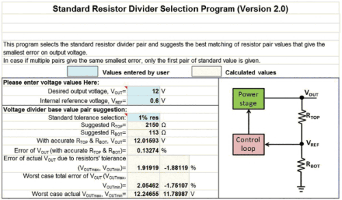
Two errors are estimated with this tool:
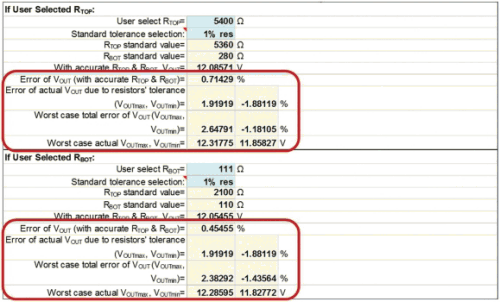
1) Error caused by standard, discrete resistor values. Note: for a given VOUT and VREF, the tool automatically selects the best matching pair of standard resistor values to minimise this error, so the actual VOUT is closest to the target value.
2) Error caused by resistor tolerance for a given VOUT and VREF combination. In fact, with a pair of 1% accurate resistor dividers, the effective divider tolerance becomes a function of the divider ratio, in the range from 1% to 2%.
The LTpowerCAD resistor divider tool sums those two errors for the total R-divider tolerance. This makes it easy for an engineer to view the total error to decide which resistor tolerance level (0,1%, 0,5%, 1% or 2%) will be necessary to meet the final target.
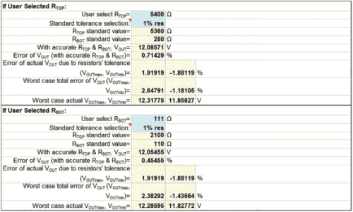
The tool also has a provision to solve either the top or bottom resistor value when given the other resistance (user input) while also considering the target or allowable component tolerance. Aside from the resistor value recommendations, the tool also shows the error computations associated with a component tolerance with respect to the ideal and actual VOUT.
With these parameters, designers can get a glimpse of the expected voltage range, given the chosen component tolerances and assess if it fits the target application.
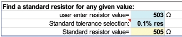
Lastly, the tool also has a feature for finding standard value resistors for any given value to help simplify the component search.
Additional errors and considerations
It is necessary to point out that this resistor divider tool only estimates the DC error by the resistor divider. It does not include other DC errors that should be added to the resistor divider error for the total power supply VOUT regulation accuracy. These additional errors include:
1) An IC internal reference VREF error, which is typically in the range of 0,5% to 1,5% and can be found on the IC data sheet’s EC table.
2) Power supply line and load regulation errors that can be found on the IC EC table as well.
3) ADJ or FB pin leakage current error, as in the LT3062 example, with a lower RBOT value desired to reduce this error.
4) Additional errors caused by PCB resistance between the local IC and the remote load device, etc.
All these errors should be considered for total error estimation while designing a power supply.
In addition, a high-precision electronics system may also have a strict requirement of total supply output voltage tolerance, including DC error and AC ripples. For example, many high-current ASICs and FPGAs require a ±2% or ±3% total tolerance window, including DC error and AC ripples. To meet this strict requirement, the power supply must be designed with fast transient response, as well as having large output capacitors to minimise VOUT ripple during fast load step transients. In this case, it is critical to select an IC with tight VREF tolerance.
A regulator with remote voltage sensing is desired for high-current rails. In addition, the space and cost saving of output capacitors will be much greater than the small cost increase of using a 0,5% or even a 0,1% resistor. It is also helpful to use an integrated module, such as an Analog Devices LTM series µModule regulator, that specifies the total DC regulation tolerance (including VREF, line and load regulation errors) of a complete high-performance power supply solution.
Conclusion
Depending on the target application, certain levels of power supply VOUT tolerance are required. A few millivolts of error might be a crucial aspect in different systems and so proper design considerations must be met.
One external and controllable factor in regulator accuracy is component tolerance. The difference between using resistors with 0,5% tolerance vs. 2% tolerance might have a significant impact on your system’s performance, and choosing the right components lessens the possibility of errors. Selecting the right components also helps minimise cost and improve reliability since the need for changing components would be minimised or eliminated.
Using the LTpowerCAD resistor divider tool, engineers can observe the effects of component tolerance on their power supply design. By initially choosing a target output voltage and reference pin voltage, designers can: (1) get the best matching pair of standard resistors for the target voltage, (2) solve for either the top or bottom resistor and (3) achieve the desired range of voltage error due to R-divider tolerance.
With the given features, plus the standard resistor finder, the resistor divider tool proves to be helpful in power supply design. It can especially help engineers who are beginners in power supply design to get acquainted with it. Using this tool, an engineer can design power supplies that can match the specifications needed for the intended application and ensure the optimal performance and power delivered to different system blocks.
| Tel: | +27 11 923 9600 |
| Email: | [email protected] |
| www: | www.altronarrow.com |
| Articles: | More information and articles about Altron Arrow |


© Technews Publishing (Pty) Ltd | All Rights Reserved
 printer friendly version