


LEDs, like all diodes, are current-driven devices. The light output is directly proportional to the input current provided. It is not enough to provide a constant voltage to the LED. From one LED to the next, the voltage at a specific current can vary by as much as 0,4 V. This can result in a 2:1 difference in the current supplied and will affect the power output from one LED to the next by the same ratio.
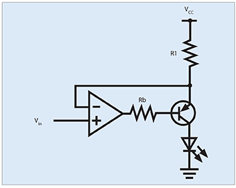
There are a few different methods for supplying current to the LED and one example of an accurate and stable circuit is shown in Figure 1.
This circuit is commonly referred to as a constant current source. Note that the supply current is determined by the supply voltage (VCC) minus Vin divided by R1. In applications where the operating temperature range is narrow (less than 30°C) or the output of the LED is not critical, a simple circuit utilising a current limiting resistor may be used as shown in Figure 2.
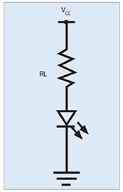
The current value is found by applying the equation I=(VCC-VF)/RL. To be certain of the current flow in the circuit, each LED VF would have to be measured and the appropriate load resistor specified. In practical commercial applications VCC is designed to be much larger than VF and thus the small changes in VF do not affect the overall current by a large amount. The negative aspect of this circuit is a large power loss through RL. In a few instances, primarily in the surveillance industries, current-limited power supplies or batteries are used as the power source. If the supply has a maximum current rating less than the LED maximum rating, it can be connected directly without any associated electronics. Please note that this is not a method that is recommended but it has been used with varying success by end users. For pulsing applications it is important that the LED be driven by a low-impedance driver. Opto Diode recommends a low impedance FET output for the final driver stage. If this is not possible, then a load resistor must be placed between the LED and output driver to minimise any inductive spikes that may occur. Instantaneous damage to the LED chip may occur if the circuit is not properly connected. For breadboard prototyping or small production runs it is recommended that an off the shelf laser diode driver be used to pulse the LED.
Peak wavelength, forward voltage and power output are all affected by changes in the junction temperature. The junction temperature in a given circuit is affected by the input current, ambient temperature and level of heat sinking of the package.
Peak wavelength
For applications where an optically unfiltered photodiode is the receiver, the shift in wavelength is not critical. However, for wavelength specific applications such as a CCD or night vision goggle illumination, high junction temperatures can play a critical role. The wavelength shift is typically 0,35 nm per 1°C shift in the junction temperature. For instance, if the junction temperature rises from 40 to 100°C, the wavelength may shift from 885 nm to 906 nm.
Forward voltage
The forward voltage gets smaller as the junction temperature increases. The typical shift is approximately –0,1%/°C. This can be important if the current source does not have enough headroom at low temperatures to support the increased forward voltage of the LED. If the figure 2 circuit is employed at high temperatures the current will increase and may potentially damage the device due to excess current and junction temperature.
Power output
The power output efficiency of near IRLEDs decreases by approximately -0,5%/°C. In applications where there are large temperature swings, the variation in LED output will be far greater than the drop in LED power output caused by long-term degradation.
Safety standard applicable to LEDs
In the United States, ANSI Z136.1-2000, American national standard for safe use of lasers, is the standard used to define emission limits for lasers. Appendix H of this standard refers manufacturers to ANSI RP27.1 and RP27.3 to apply safety standards for LEDs. Western Europe, and other countries, apply IEC 60825-1, safety of laser products as the standard for LEDs and lasers. This document does not make a distinction or apply different emission limits between LEDs and lasers. Reflector cups, multiple LEDs, external lenses and/or other optical components applied by the equipment manufacturer may significantly alter the emission level. It is the responsibility of the equipment manufacturer to test and verify the actual emission in the system.
| Tel: | +27 11 608 0144 |
| Email: | [email protected] |
| www: | www.nuvisionelec.com |
| Articles: | More information and articles about NuVision Electronics |


© Technews Publishing (Pty) Ltd | All Rights Reserved
 printer friendly version