


We usually think of solder balls when talking about spatter. There is a certain similarity between solder balls and spatters. However, the industry defining two kinds of defects is mainly due to the generation of solder balls and the solderability of tin powder. There is a great correlation with cleanliness of printing wipes. When the bottom of the stencil is not completely wiped, a single or a few tin powder particles adhere to the bottom of the stencil and are transferred to the PCB to form a solder ball during PCB printing. If to simply distinguish the solder ball and spatter, the cleanliness of the surface under the magnifying glass can be checked after printing on the PCB. If the surface of the PCB is very clean before going through the oven, then the solder ball can be defined as the spatter produced during reflow.
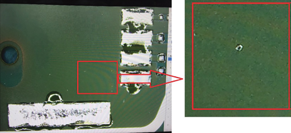
Splash is mainly caused by the influence of moisture in the environment leading to water molecules entering the solder paste. During reflow, the solvent and water molecules in the solder paste volatilise too quickly to form an explosive vapourisation phenomenon due to rapid temperature rise. Therefore, when the solder paste is placed in a humid environment, or a more hygroscopic solder paste is used, splashing is more likely to occur. A typical example is that the solder ball is more likely to be produced with water-soluble solder paste than no-clean solder paste. The generation of spatter may also be caused by the coagulation of solder paste. During the preheating process, the flux removes the oxide on the surface of the solder powder, and numerous tin powder particles melt and fuse together as a whole, while the flux adhering to the surface of the solder powder is squeezed out. The faster the wetting rate, the stronger the cohesion of the solder powder is, resulting in the easier production of spatter. Figure 1 shows an example of solder spatter.
Based on these principles, two sets of experiments were designed to study the effect of optimising the reflow profile on spatter.
Experiment 1
Four mainstream lead-free, halogen-free solder pastes were selected to compare the effects of different types of solder paste, flux ratio, and temperature ramp on spatter. These solder pastes were identified using generic names of paste A, B, C and D respectively.
Solder paste B was matched with two different metal loads, 88,25% and 88,75%, respectively, to observe the effect of different flux content on the splash. For the reflow profile, two linear temperature profiles with temperature ramps of 1,9°C/s and 1,2°C/s, respectively, were selected, as shown in Table 1.
Experimental steps:
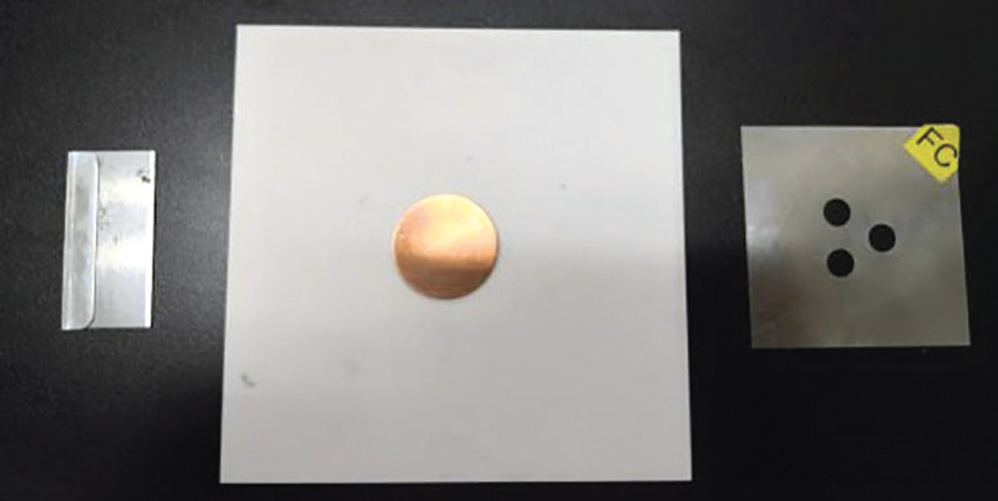
1. According to the IPC-TM-650 2.4.45 wetting test, a round copper sheet, a three-hole stencil with a thickness of 0,254 mm, and a circular opening of 6,35 mm was used to print the solder paste, as shown in Figure 2.
2. The copper sheet was placed on a 4 x 4-inch ceramic square.
3. This was placed in an oven for reflow, and spatter from the solder paste on the copper sheet onto the ceramic sheet was observed with a microscope and marked with a red marker.
Experiment results
Figure 3 shows the results of this experiment. Solder Paste A showed the least amount of splash; Solder Paste C had the most spatter with about 200 splash points appearing on the ceramic wafer; and the performance of Solder Pastes B and D were found to be relatively close. Therefore, different types of flux will bring about a significant difference in solder paste splash.
It was observed in the Solder Paste B experiment that adjusting the metal load, 11,75% and 11,25% of flux content, did not significantly improve the reduction of splash.
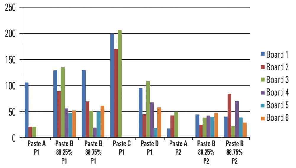
Under different reflow profile, with the slow temperature ramp and 50 s extension of the soak temperature of 25 to 217°C, the amount of spatter was relatively reduced by about 30%.
Experiment 2
This experiment took place on a production line of a car electronics customer. The PCB was the actual product of the customer, and Solder Paste B (metal load 88,25%, SAC305) was used. The reflow profile was adjusted to observe the amount of spatter.
Step 1:
The solder paste was printed on the PCB using reflow profile P3, as shown in Table 2. The maximum temperature was 205°C, lower than the melting point of the SAC305 alloy, to determine whether the spatter is generated by the moisture absorbed by the solder paste in the air.
Through experiments, no spatter on the PCB surface was found. This indicated that the spatter was not caused by the moisture absorbed by the solder paste, or that the surface tension of the solder paste is very low before the solder paste reaches a liquid state. The flux was easily volatilised from the solder powder, and did not form a sharp vapourisation explosion.
Step 2:
The peak temperature was increased to 245°C, with a reflow time of 50 seconds, as shown in profile P4 in Table 2. The printing paste passed through the oven, and a large amount of spatter was generated on the surface of the PCB after going through the oven, as shown in Figure 4.
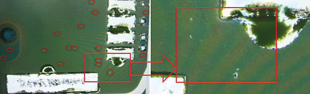
It was determined that the spatter was generated after the liquefaction of the solder paste. This is due to the vapourisation explosion caused by the rapid extrusion of the flux, which had not been volatilised under the coagulation of solder powder. Therefore, a large amount of splash was generated.
It is well known that on the line, the rate of coalescence of solder powder is very fast, and the entire agglomeration reaction is completed in two to three seconds. That is to say, the vapourisation explosion of the flux occurs immediately after reaching the 220°C alloy solidus line. It is then almost impossible to reduce spatter by adjusting the liquidus area.
The board that was blasted in Step 1 (that is, the solder paste that had not reached the melting point of the solder paste, equivalent to pre-baked board) was again blasted with profile P4. The surface of the PCB was observed to have no spatter. This indicated that a large amount of consumable flux of pre-bake helped reduce spatter. This was consistent with the results of the effect of the heating rate and the constant temperature on the spatter of Experiment 1. Since most of the fluxes are around 200°C, is it effective for the spatter to stretch the baking time near the liquidus area and try to let more flux volatilise. Based on this, step 3 of the experiment was carried out.
Step 3:
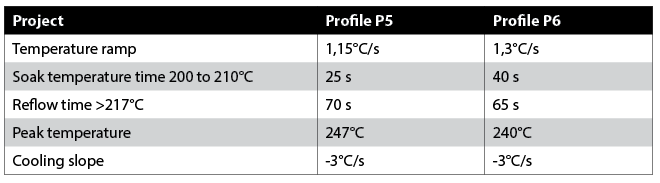
Two different soak temperature profiles were used, shown in Table 3, to print the solder paste and pass it through the oven. Baking time of profile P5 was changed to 25 seconds, and that of profile P6 to 40 seconds.
Experiments showed a small amount of spatter on the PCB board using the P5 profile, and the spatter ratio was reduced by about 80% compared to the conventional SAC305 curve P4. The PCB spatter using the P6 profile was further reduced, and almost no splash was observed.
Summary
Splash is a problem that solder paste will inevitably encounter during the welding process. Distinguishing between spatter and solder ball is the first step to solve the problem.
Different types of solder pastes have different effects on splashing, which may be related to the amount of hydrophilic molecules in the flux formulation or material. Water-soluble solder paste is more prone to splashing than the no-clean solder paste. Reducing the flux content of the solder paste does not significantly contribute to the generation of spatter.
In this experiment, it was found that the spatter was produced after the liquefaction of the solder paste. Splashes were rapidly reduced as the baking temperature was increased and the baking time extended. Because the surface tension of the solder paste was very low before the liquidus, the flux was easily separated and evaporated from the solder powder particles, and more oxide was generated. This reduced the propelling force of the solder powder, making it harder for the flux to be squeezed out by coagulation.
Taking into account the boiling point of the flux, increasing the baking time between 200 and 210°C quickly helped to fully consume the volatiles in the flux. Due to the thermal deformation of the component or PCB and the oxidation of the metal, the baking time of 200 to 210°C cannot be extended indefinitely, and the specific limit must be confirmed with the solder paste manufacturer.
| Tel: | +27 11 824 1427 |
| Email: | [email protected] |
| www: | www.techmet.co.za |
| Articles: | More information and articles about Techmet |


© Technews Publishing (Pty) Ltd | All Rights Reserved
 printer friendly version