With the frequent load shedding in South Africa, finding an offline source of power at home has become a necessity. Simon Brumble, staff engineer at Analog Devices shows how to build a home UPS using a car battery as a backup source. The battery is connected to a buck-boost converter that generates a stable 12 V 5 A supply to power the Wi-Fi router, as well as a 6,5 V 1,5 A buck converter to charge a mobile phone.
An uninterruptible power supply (UPS) for your home
As the world becomes more advanced, our dependence on electricity becomes more acute. Power outages can reduce the most sophisticated homes to quite primitive ones and this article describes the design of an uninterruptible that keeps alive the home’s most essential service: Wi-Fi.
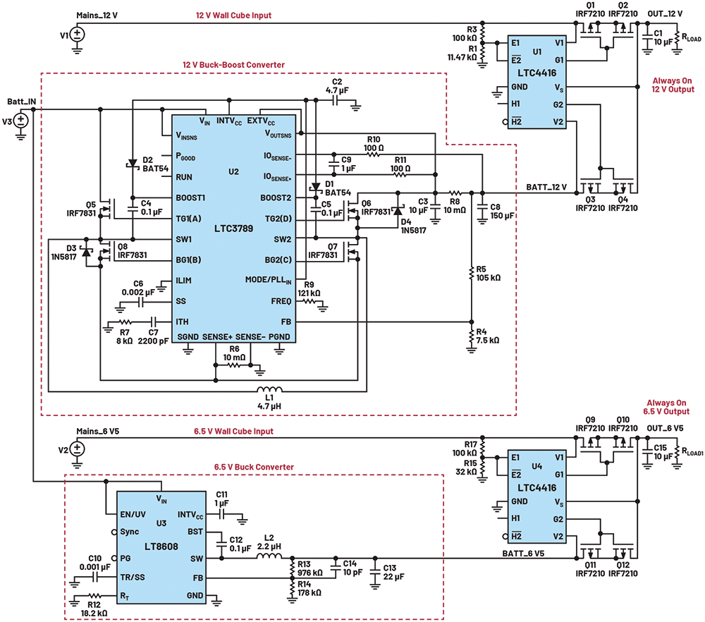
The circuit in Figure 1 was designed out of necessity. With the threat of an energy crisis looming in early 2022 and world peace on a knife’s edge, it was designed to keep home Wi-Fi alive in the case of a power outage. While this might be seen as a first world problem, it takes over two minutes for the average Wi-Fi router to reboot, and this can seem like an eternity if the power disappears in the middle of a conference call. Even minor dips can cause major problems. This home use uninterruptible power supply design provides a 12 V 5 A power supply for the Wi-Fi access point
The circuit is shown in Figure 1. The backup power source for this design was a pre-loved car battery purchased from a scrapyard for a little under R400. The LTC3789 is a four-switch buck-boost converter that provides a constant 12 V supply, with extremely high efficiency, from an input that could be above or below this voltage. Its evaluation kit provides 12 V at 5 A from a 5 V to 36 V input voltage, so it could be used with no modification. Since the Wi-Fi router only needed 1 A, this evaluation kit could be used to power many other appliances simultaneously that require 12 V.
The mobile telephone required 6,5 V at about 600 mA, so the LT8608 was chosen to provide this rail with low noise and high efficiency with an extremely low quiescent current of 2,5 μA. The LT8608 and LTC3789 have maximum input voltages of 42 V and 38 V, respectively, so they were connected directly to the car battery for the highest circuit efficiency.
Some lower cost battery chargers can generate high voltages if they are not connected to the battery correctly, so the battery does not adequately absorb the charging current. Therefore, if the charger has a good connection to the circuit, but a poor connection to the battery, a voltage can be generated that might damage the electronics. The wide input voltage range of the LTC3789 and the LT8608 alleviated concern of high voltages being generated when the battery charger was connected. The circuit can be operated either with the battery charger permanently connected or not. However, the safety aspect of keeping the battery charger permanently connected in an unventilated room depends on the type of the battery and charger used.
The clever part of the circuit was provided by the LTC4416. This is a dual ideal diode and was responsible for switching between the main supply voltages and the backup supplies. The LTC4416 contains a precision comparator that detects when the main supply has failed and switches over to its backup supply using four external P-channel MOSFETs (PFETs).
A simpler form of this circuit is a dual diode OR configuration where the cathodes of two diodes are joined, and the main and backup supplies are connected to the anodes. However, this circuit only feeds the highest of the two supplies to the output at the cathode as well as incurring a loss of 0,6 V across the diode. A more efficient circuit can be designed using PFETs to replace the diodes. The voltage drop across the body diode of the PFET is measured and if this exceeds a certain threshold, the FET is switched on, thus shorting out the body diode. If this voltage drop goes negative, the drive to the PFET is removed and the body diode blocks the reverse current. Thus, an ideal diode has been created that has a low forward voltage drop and blocking in the reverse direction. This is shown in Figure 2.
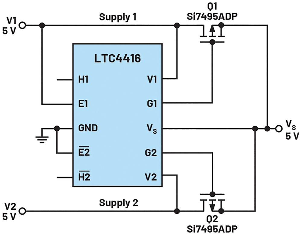 Figure 2. An ideal diode implementation of the diode OR circuit.
With this circuit, the body diode of each PFET points from the input to the output, so if one input voltage is higher than the other by more than 600 mV, this body diode will conduct. Therefore, if the backup supply happens to be higher than the main supply, the load’s power will be supplied by the backup supply, which is undesirable. Reversing the PFET stops this problem, but then the body diode conducts if the output voltage is higher than the input voltage by more than 600 mV.
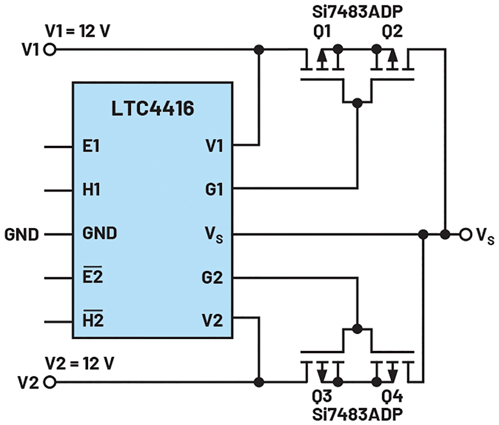 Figure 3. A diode OR circuit with bidirectional disconnect.
A cleaner solution is to add an additional PFET to each path as shown in Figure 3. In this circuit, the two body diodes oppose each other so this circuit provides a bidirectional open circuit when the FETs are switched off, and isolates each channel regardless of the input or output voltages.
For the 12 V circuit, the evaluation kit of the LTC4416 (DC1059A) was modified to give a switch-over voltage of 11,17 V, using a 100 kΩ resistor for R3 and a 10 kΩ + 2,2 kΩ resistor for R1. This worked well, but it was found that the Wi-Fi access point needed a precise 12 V supply and sometimes it rebooted when the main 12 V was switched back on again. This was due to the voltage step
The mobile telephone circuit was much more sympathetic to power supply steps, so R15 comprised of a 22 kΩ + 10 kΩ resistor, giving a switch over voltage of 5 V.
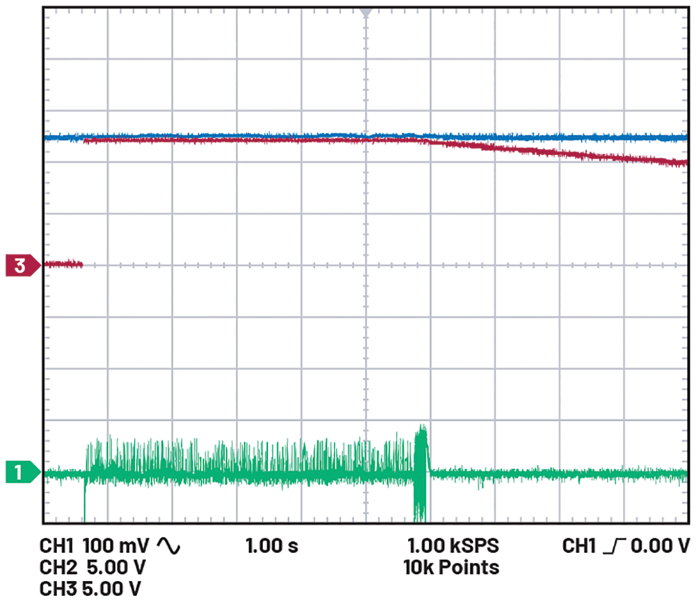 Figure 4. 12 V (green trace) is hardly disturbed when the mains (red trace) is disconnected.
The waveforms can be seen in Figure 4. The green trace shows the always on 12 V output from the LTC4416, the red trace shows the 12 V output from the wall cube, and the blue trace shows the car battery voltage. The disturbance to the green trace could not be seen when the oscilloscope was DC coupled. Changing to AC coupling shows little disturbance when the mains 12 V is connected (at 600 ms) and disconnected (at 5,8 s). Ironically, the noise on this rail was significantly higher when the mains 12 V was connected, showing that the noise from the wall cube output was higher than that from the LTC3789.
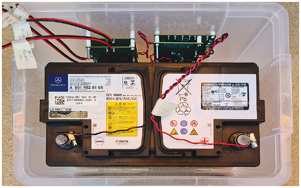 Figure 5. The complete circuit with battery.
A photograph of the complete circuit is shown in Figure 5.
Future modifications
The circuits previously mentioned require the cables from the wall cubes to be cut to allow the UPS to be inserted in series. A neater solution would be to generate, say, 340 V DC from the car battery and feed this into an extension socket, then plug the wall cubes into the extension socket. Since the circuitry inside all wall cubes contains a rectifier, it would not matter if this voltage was AC or DC. However, the losses incurred in generating 340 V from a 12 V battery as well as the losses incurred in reducing that voltage down inside the wall cube meant that a low voltage circuit would be far more efficient and simpler, even if it did mean cutting the wall cube cables.
The LTC4416 evaluation kits included LEDs to indicate whether the main or backup power supply was being used and these could easily be brought to the outside casing. Another useful addition would be a push button switch to artificially pull the LTC4416’s enable pins low to test the switch-over functionality.
The circuit was tested extensively and found to give excellent performance. For higher currents, N-channel ideal diodes are available. The LTC4416 is part of a wide range of ideal diodes and hot swap devices available from Analog Devices.
Conclusion
The circuit described in this article illustrates the design of a simple home use uninterruptible power supply that can be built to keep various home appliances alive in the event of a power failure. There is no reason why this circuit cannot be modified to use more powerful MOSFETs and a larger battery to give an increased output power and a longer backup life.
| Tel: | +27 11 923 9600 |
| Email: | [email protected] |
| www: | www.altronarrow.com |
| Articles: | More information and articles about Altron Arrow |


© Technews Publishing (Pty) Ltd | All Rights Reserved
 printer friendly version