


Vinaya Skanda from Microchip Technology shows the significance of the op-amp in certain applications, such as measuring vital signs on the human body.
The ubiquitous presence and influence of the op-amp exists across the length and breadth of the electronic world. In some applications, they play a significant role. These include medical electronics, power supplies and even some generic signal processing and measurement applications.
Knowing the characteristics of an operational amplifier (op-amp) is vital when choosing it for a specific application, which in turn calls for knowing the application requirements well. While certain routine applications can be accomplished using popular rules of thumb, a more thorough analysis of the characteristics is needed when the performance requirements are severe. Here, the designer will need to look at some of the non-ideal parameters and characteristics of the op-amp.
Applications considered include digital power converters, control systems and medical electronics, where they can play a key role in devices for measuring the vital parameters of the human body.
Stability
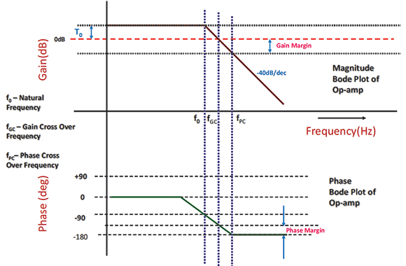
For an op-amp system to be stable, the closed-loop response must resemble a single-pole response. If the closed-loop gain intersects the open-loop gain at a rate of 20 dB/decade, then the system is stable. When the point is reached where the closed-loop response falls at 40 dB/decade, the op-amp will oscillate. One pole adds a 90° phase and hence two poles add 180° of phase. Once 180° is added into the feedback path, the negative feedback system transforms itself into a positive feedback system and will start producing oscillations.
As shown in the Bode phase plot of a generic op-amp in Figure 1, phase margin signifies the phase shift at unity gain that is left to approach the 180° point. Phase margin is one of the figures of merit for analysing the stability of an op-amp. As can be seen from Figure 1, the change in the phase does not necessarily happen at the corner frequency. Instead, the phase starts changing a decade back from the corner frequency itself. A phase margin of about 40° under standard operating conditions is typical of an on-chip op-amp on a Microchip PIC16F microcontroller.
Measuring circuits
Op-amps form a key component when designing any analog or mixed-signal power supply. They find use in both signal measurements and compensation networks. A very common use of an op-amp in digital power converters is in the measurement of current flowing through the inductor. Similarly, in the case of motor control and energy metering, it is used in measuring current flowing through the phases of the inverter. Often, a sense resistor is used in series in the path of the current flow of the phase, as shown in Figure 2.
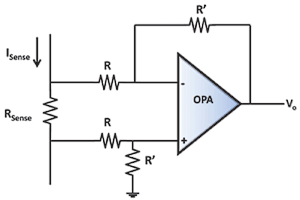
The voltage drop across the sense resistor is then amplified and fed back to the analog-to-digital converter of the microcontroller. Since the value of the sense resistor will usually be very small – of the order of a few milliohms to a few ohms – amplification of the measured voltage is necessary. An op-amp is thus used in a difference amplifier configuration so, irrespective of the direction of current flow, the voltage difference is faithfully amplified.
A microcontroller such as the PIC16F753, having a single op-amp on chip, would be suitable for this type of application. The op-amp being internal to the controller would reduce the overall cost of the design and save board space. Immunity to noise will improve as there will not be as many traces on the board as would be required when using an external op-amp.
Control systems
If an analog control approach is taken when designing a power converter operating in buck or boost topology to regulate the output voltage, the control system invariably requires a compensator using an op-amp. A compensator that has three poles and two zeroes is normally required if the control method uses only the output for control. This is referred to as voltage mode control and is commonly called a type III compensator.
Such a compensator is a small variation of the inverting amplifier in terms of changes in the feedback network. The feedback network is suitably designed to provide a transfer function that has three poles and two zeroes. A loop crossover somewhere between the zeroes and the poles can be achieved if the two zeroes coincide at one frequency and the two poles coincide at one frequency. A reasonable phase margin can be met using such compensators since a good amount of boost in the phase is possible.
Medical electronics
Bioelectrochemical sensors are essential in most medical equipment used for monitoring vital parameters of the human body. The biosensors often involve electrochemical activity taking place in microbes, enzymes or chemical compounds. These activities need to be tested, measured and, in some cases, controlled.
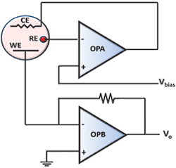
One common electronic circuit used in such applications is the potentiostat or galvanostat. This is needed for the proper operation of a bioelectrochemical sensor. In applications such as odour and taste detection sensors, a bank of potentiostats may be needed. In the simple arrangement of a potentiostat in Figure 3, there are two op-amps used. A PIC16F1793 or PIC16F1786 would suit because these devices have two internal op-amps.
A potentiostat is a three-electrode cell consisting of working electrode, reference electrode and counter electrode. The counter electrode conducts current into or out of the cell, and this current has to balance the current generated at the working electrode. The reference electrode provides a reference for the working electrode to measure the electrolyte’s potential.
The amplifier is responsible for maintaining the voltage between the reference electrode and the working electrode as close as possible to the voltage Vbias connected to the non-inverting terminal. Its output is controlled to maintain the cell current so equilibrium is achieved.
The potentiostat has to measure the current from the working electrode and deliver a useful signal at the output terminal. This current can be bipolar and is measured irrespective of whether the current flows in or out of the working electrode.
Low-frequency sensors
Op-amps can also be used for generating low-frequency circuits for sensors that use a technique called correlation to detect the presence of low-frequency signals. The signal to be tested or detected is correlated with a reference low-frequency signal, and it is this reference that is generated in the op-amp circuit.
Typical applications include pipeline leak detection, locating hot spots and radiation from electrical appliances, seismic wave detection, smoke and fire alarms as low-frequency tones are better for those with poor hearing, and pressure sensors for engine combustion and turbulence detection.
In these types of application, the performance of a standalone op-amp is very similar to that of an internal op-amp in a PIC16F microcontroller, and being internal means fewer components are needed. There is also an improvement in immunity to external noise since there is no need for traces to connect the op-amp.
| Email: | [email protected] |
| www: | |
| Articles: | More information and articles about Tempe Technologies |






© Technews Publishing (Pty) Ltd | All Rights Reserved
 printer friendly version