In the near future, only lead-free electrical and electronic products will be permitted under European legislation. Research studies by Tyco Electronics Power Systems show that series production of complex electronic components in lead-free versions is possible today using existing soldering machines with no loss of quality.
European Union directives are intended to eliminate or minimise hazardous substances such as lead, cadmium and polybrominated materials from 2006 onwards. As lead is an essential component of the solder used today, this legislation will affect almost all manufacturers of electrical or electronic products. Most large electronics manufacturers have already begun searching for suitable alternatives and it is expected that a range of lead-free products will be available on the market even before the above cut-off date. As well as the image benefits, an early market presence will also bring companies tangible competitive advantages, as similar legislation will be coming into force much earlier in other countries, for example Japan.
The procedure adopted by Tyco Electronics to make their products lead-free as required can be described as follows.
* Search for a suitable solder.
* Analysis of manufacturing options.
* Selection of suitable components.
* Identification of appropriate quality tests.
Lead-free solder
In terms of selecting a suitable lead-free solder, taking into account criteria such as global availability, patent freedom, melting point, chemical properties, compatibility with other components and cost, the following products are particularly relevant: tin/silver solder (Sn-3.5Ag) with a melting point of 221°C and tin/silver/copper solder (Sn-3.8Ag-0.7Cu) with a melting point of 217°C. It was decided to use the tin/silver/ copper solder, as its melting point is only 34°C above that of tin/lead and it offers a slightly larger distance from the target maximum solder temperature of 245°C.
Soldering equipment
Standard industry reflow soldering ovens with 10 to 11 heating zones and two to three cooling zones were used. The number of heating and cooling zones has proved to be an important parameter in achieving more targeted control over the temperature.
Suitable components
Most components available today are suitable for the target peak solder temperature of 245°C on the components and are either already available with lead-free contacts or the finish can be converted to pure tin, tin/silver or other combinations with relatively few problems. Limiting the solder temperature to 245°C also has the advantage that it is possible to fall back on the component manufacturers' reliability data that exists for almost all components at that temperature. By contrast, inadequate quality data is available for higher solder temperatures, eg, 260°C.
On technological grounds, some components, for example ceramic capacitors or certain ICs, require lead inside the component for contacting purposes. In this case, conversion is not so easy and requires more extensive research by the component manufacturers. Limited use of such components in lead-free products is still possible in principle, however, as the legal requirements allow residual quantities of lead (currently 0,1% of the total weight of the end product). If lead-free solder, lead-free component connections and lead-free circuit board pads are used, this limit can be met.
Quality tests
The tests previously used to assess the quality of soldered connections to IPC/JEDEC standard J-STD020 can, to a great extent, continue to be used. At some points, such as the paste viscosity, adaptation to the special features of lead-free solder is necessary.
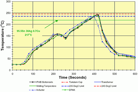
The proposed process for the manufacture of lead-free products on standard industry soldering equipment has been verified using numerous test series. The products processed were various standard DC-DC converters with dimensions of 57 x 60 x 12 mm, which were soldered in panels with dimensions of approximately 203 x 280 mm. As a reflow solder profile, the linear profile recommended by the solder paste manufacturer was used, with a temperature increase of less than 1°C/s, a cooling speed of approximately 3°C/s and a maximum component temperature during soldering of between 235°C and 245°C. The maximum time above melting point, ie above 217°C, should be kept below 60 seconds, with around 15 seconds above 235°C.
This linear solder profile differs from the profiles that are currently often used in reflow soldering systems, which have longer pre-heating at an almost constant temperature and subsequent rapid temperature increase for the actual reflow process. These profiles were originally developed for infrared soldering systems and could be replaced by the linear profile described with no problems, even when using solder containing lead. In most cases, this would even lead to an improvement in quality due to lower thermal loads on the components. By way of example, Figure 1 shows the measured temperature progression on components of different sizes on a DC-DC converter during the soldering process. The brief temperature fall after 230 seconds can be traced back to the failure of a heating zone. It was possible to keep the maximum component temperature within the desired temperature band of 235°C minimum to a maximum of 245°C. This guarantees reliable melting of the solder, without the temperature load on the components moving outside the range validated by the manufacturer.

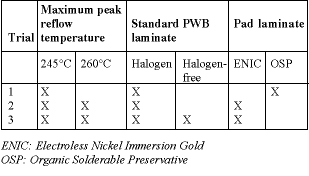
One part of the DC-DC converter was processed with a linear solder profile and a maximum temperature of 260°C. The reason for this was to gather information about the way in which higher peak temperatures affect the soldered connections in lead-free processes and the reliability of the components and the end product. As well as standard circuit boards with halogenated coatings, halogen-free products were also analysed. Table 1 provides an overview of the investigations carried out.

All modules were subjected to extensive tests, after having been reflow soldered three times. The quality of the soldered connections achieved with this lead-free process was verified by way of visual checks and cross sections of the soldering points at representative components of different sizes and with different connecting contacts. The cross sections were made before, during and at the end of a temperature load test comprising 1000 cycles, in which the ambient temperature was changed from -55°C to +125°C or vice versa within an hour. The modules also underwent shock and vibration tests, as well as a moisture sensitivity level (MSL) test. In this test, carried out to JEDEC standards, the modules were initially exposed to an 85°C ambient temperature with 85% relative humidity for 168 hours, before being reflow soldered a further three times. This was designed to test how extreme climatic conditions, which are extremely common in some parts of the world during transportation and storage, and the increased maximum solder temperature affect the components used.
In parallel, the electrical parameters of the modules were checked before and after the individual tests, in order to uncover any invisible effects on the components.
The tests all confirm that the lead-free process described here results in good, reliable soldered connections. There was no loss of quality compared to the previous standard processes using solder containing lead. On the contrary, the narrower process tolerances tend to increase the quality of the final product. Limiting the maximum solder temperature to 245°C does not result in any problems with the moisture enclosed in the components, and all modules produced in this way meet the requirements of moisture sensitivity level 1. The linear reflow solder profile is tremendously helpful here, as it prevents rapid temperature changes, which can otherwise lead to components bursting apart if the enclosed water content evaporates abruptly. The use of only a slightly higher maximum solder temperature of 260°C instead of 245°C led to problems in this area in some cases. Tyco Electronics is currently carrying out more extensive investigations into this.
The test results also show that certain critical components require further development by their manufacturers, in order to be able to withstand the higher solder temperatures without damage. Until reliability data for 260°C is available for most components, it is recommended that the solder temperature is limited to 245°C, which as demonstrated above can be achieved with no problems. With the process described above, the anticipated additional costs for the elimination of lead are estimated to be negligible. No investment in new soldering equipment is necessary and the costs of lead-free tin/silver/copper solder and halogen-free circuit boards will fall quickly when used in mass production.
For more information contact Robert Reynolds, Arrow Altech Distribution, 011 923 9600, [email protected]
| Tel: | +27 11 923 9600 |
| Email: | [email protected] |
| www: | www.altronarrow.com |
| Articles: | More information and articles about Altron Arrow |

© Technews Publishing (Pty) Ltd | All Rights Reserved