


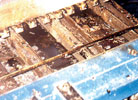
Today, the most common type of wave-soldering conveyor is the finger system. Although more expensive than the chain system, finger conveyors are more versatile as the conveyor may be opened and closed for different board widths. They also allow direct and automatic loading of boards from an in-line feed conveyor, helping to automate the wave soldering process.
With many companies trying to reduce time during machine set-up, jigs and pallets can overcome the issue of different width boards without introducing standard width multipanels. However, they add to manufacturing cost and many people adopting lead-free have not considered the issue of pallet contamination. You can realistically use wave-soldering pallets on lead-free and tin/lead lines. Any process engineer will say it is very difficult to clean the pallets successfully, and often, no one bothers that much anyway. With many metallic fixings, solder can be transferred between baths, which leads to a very costly mistake.
In many cases at the design stage, jigs can be eliminated if the board is narrow (less than 100 mm) or if a mechanical wave support is used and provision has been left in the layout of the bottom of the board. This can reduce processing costs and improve soldering results. With the move to lead-free wave soldering, the temperatures of the solder wave are increasing from 245°C to 260°C. This increases the degree that a board will sag during preheat and wave contact. If a chip and lambda wave are used, the board will drop a 1-2 mm and then further as it goes through the second wave. The result is a process out of control and often, a flooded board assembly.
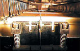
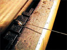
A wave support is a titanium knife edge that is positioned in the centre of the wave - often offered on Korean and Japanese machines.
The knife is supported on two adjustable rods at the front and rear of the solder pot. This allows the knife to be re-positioned for different board types. A further alternative and probably more popular, is a support wire that is again fixed to the rear of the solder pot and can be stretched through the complete machine from the fluxer to the end of the wave, and even to the exit, as the board passes through a cooling phase. This provided the ideal support and better than any solder pallet design.
Both of these techniques have been around in the industry for years. They have been very popular when single-sided boards are processed due to the use of paper-based substrates. 'Lead-free' has increased the interest in an old technique that should always have been on process engineers' shopping lists.
During soldering, the PCB substrate rises in temperature above its glass transition temperature (Tg) of 140-145°C. Even if a pallet supports a board on all four sides, the board will still tend to sag in the centre. This will always increase the possibility of shorting in the centre and back portion of the board during exit from the wave. The degree to which sagging will occur will be influenced by the following:
* Type of board: single, double-sided or multilayer.
* Location and weight of components.
* Copper balance of the circuit pattern.
* Preheat and wave temperature settings.
It has been suggested to change PCB base materials, but there is a lot of reluctance here due to the cost. Even if a higher Tg material, say 170°C, were used, the boards still go through a change of state and sag above this temperature and require process support.
A simple way of reducing this if a pallet must be used, is to use a wire fixed and recessed on the underside of the jig. This will support the board during processing and minimise distortion. Support wires like wave supports need to be considered at the PCB design stage. During layout, a no-go area should be placed along the centre of the board on its longest dimension. This no-go area should be 3-4 mm wide and should not allow any component termination points or component bodies on the base of the board. The no-go strip does not need to be perfectly in the centre as even slightly offset provides acceptable support.
It is perfectly acceptable for circuit tracking to be placed across this area as the tracking will be protected by the solder mask. If possible it is also good practice to have an indicator to the position of the no-go area on the top side of the board either in the etched copper, legend or an image in the resist. This mark should be on the back and the front of the panel and makes positioning of the wire or knife support easy during wave set-up. If the support is not positioned correctly it could interfere with other parts on the base of the board being soldered.
Either of these static solutions is simple to implement if considered at the design stage. They can be very cost effective if designed in-house and are often reasonable from suppliers. If you are considering a new machine for lead-free, think about wave supports - they are simple and provide the ideal support for board assemblies.
About the author: Bob Willis is a process engineer providing engineering support in conventional and surface mount assembly processes. He runs production lines for suppliers at exhibitions and also provides seminars and workshops worldwide. He has one of the largest collection of training videos, interactive CD-ROMs and training material in the industry. These complement his own hands-on lead-free workshops at customer sites. For further information on how Bob Willis may be able to support your staff contact him via his website at www.askbobwillis.com


© Technews Publishing (Pty) Ltd | All Rights Reserved
 printer friendly version