Manufacturing / Production Technology, Hardware & Services


Double sided reflow in one reflow cycle

5 August 2009 Manufacturing / Production Technology, Hardware & Services

In any process there are always opportunities to improve, reduce the number of process stages or reduce the cost of manufacture. Each may not improve yield initially, and may even increase manufacturing defects, but it must in time benefit some companies’ processes or products.

Engineering is always looking at alternative processes and simultaneous double sided reflow soldering (SDSRS) is a possible new candidate for investigation. It has been used by two Japanese companies, one large computer manufacturer in the USA and is reportedly being used by one other company in Europe. It was originally patented by one large US producer.

Process sequence

The process of SDSRS includes the following stages:

* Stencil print solder paste: Side One.

Figure 1. Screen printing side one is conducted in the normal way for the SDSRS process, unless solder paste dispensing jetting is going to be used for both process stages

* Dispense adhesive: Side One.

Figure 2. After the application of paste, adhesive is placed on the surface of the board by dispensing prior to component placement and curing

* Alternatively screen print adhesive: Side One (using recessed stencils).

Figure 3. An alternative to dispensing adhesives is stencil printing, which may be conducted using a recessed stencil

* Alternatively dispense paste and adhesive.

* Place components: Side One (possible UV curing stage for adhesive).

* Invert board.

* Screen print solder paste: Side Two.

* Place side two components: Side Two.

* Possibly insert through-hole components.

* Reflow solder both sides simultaneously.

Figure 4. After the second side of the assembly has been printed and components placed, the whole assembly may be reflowed in one operation reflow cycle

The question has to be asked: why consider SDSRS as it will undoubtedly cause problems with loss of components in the early stages of process development? If we examine the time taken for the reflow cycle of a product, typically this is 3 to 4 minutes. By reflowing both sides of the assembly, the total time is then 8 minutes. Clearly, by conducting simultaneous reflow, the process cycle time is reduced, with time saved on the total process cycle.

It used to be the case that placement was the slowest part of the process but with increasing speeds this is not the case. Printing was the last part of the process to be attacked by the speed merchants focusing on the solder paste specification which was the limiting factor in high-speed printing. The formulations of paste have now provided the speed to make other parts of the process the weak links in the chain with cycle speeds for printing being less than 10 seconds per board.

Advantages of SDSRS

Eliminates one reflow process stage

With simultaneous reflow soldering, both sides of a surface mount board can be conducted in one operation. If through-hole parts are also designed to be reflowed, this can be done in a single operation.

Only one heating process for double sided boards

With only one heating process there is a potential benefit to the reliability of the joints with a thinner intermetallic formation being possible. The issues related to reduction in solderability of surface mount pads are also eliminated.

With only one heating process during reflow soldering, in which the board may be supported with a central wire, it is possible to reduce warpage of boards susceptible to this problem. No hold time between reflow cycles means there are less issues of moisture with PCBs and components.

Reduction in capital equipment

Eliminating a reflow process means one less piece of equipment in a production line is required. The cost of power consumption and extraction systems for reflow equipment is higher than any other piece of equipment on the line and they are effectively halved.

Reduced floor space requirements

Eliminating a reflow oven reduces the floor space required in a manufacturing area. Even with the need for an additional printer or the use of a single dispenser for both adhesive and paste, floor space is still being saved.

Reduced handling stages

The number of handling stages is reduced compared to a conventional surface mount process, albeit only slightly reduced from a fully double-sided reflow process.

Increased PCB throughput speed

The total process cycle time for each product is reduced by the elimination of one reflow soldering stage. The increased cycle time for one printing or dispensing stage is still far less than the period taken to reflow one side of a board.

Potential elimination of component weight issues

In a liquid state there is a limit to component weight during traditional double sided surface mount assembly. Large heavy components can fall off the board. If adhesive is used and cured, it will increase the range of components that can be used on both sides of the board.

Improved solderability of OSP circuit boards

There has been great debate on the benefits of using OSP: improved printing and placement, cost reduction and improved yields. OSP coatings have been shown to deteriorate during two reflow cycles; with one reflow process stage the problem is eliminated. It is the opinion of the author that most of the problems seen on OSP coated boards stem back to the quality or preparation of the original coating. Potential users of OSP should understand some of the simple process evaluation techniques or goods receipt tests.

Disadvantages

Of course, no process is perfect, and there are certainly disadvantages to SDSRS.

They are:

* New process introduction.

* Possible loss of components.

* Gluing stage required.

* New glue materials required.

* Glue curing process.

* Possible limits on component positioning.

Examples

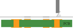
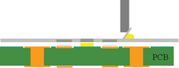
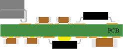
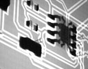
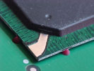
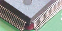
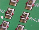
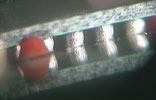
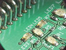
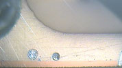
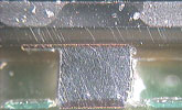
Figures 5 to 8 illustrate examples of joints produced with this process and tin/silver/copper solder paste reflowed in a single convection cycle in air.

Figure 5. X-ray images illustrate BGA and surface mount components reflow soldered on the base of the board during simultaneous reflow

Figure 6. Example components that have been reflowed on the base of the board with the adhesive holding the parts in place during a single reflow soldering cycle in a convection oven

Figure 7. Bottom sided images of chip resistors and BGA terminations and a top sided view featuring successful reflow of LED and intrusive reflow connector joints

Figure 8. Microsections of chip termination and a BGA package after reflow

For more information visit www.askbobwillis.com


Share this article:
Share via emailShare via LinkedInPrint this page

Further reading:

Yamaha reveals software innovations to boost printing, mounting, and intelligent factory
Truth Electronic Manufacturing Manufacturing / Production Technology, Hardware & Services
Yamaha Robotics Europe SMT Section has added new features to native equipment software and Intelligent Factory tools that accelerate equipment programming, increase production efficiency, and enhance factory productivity.

Read more...
UltiMaker introduces defence-grade 3D printing
RS South Africa Manufacturing / Production Technology, Hardware & Services
Leading at launch are the UltiMaker S6 Secure and UltiMaker S8 Secure, two robust solutions designed to deliver trusted and reliable, on-demand production capabilities.

Read more...
The future is built by hand
Manufacturing / Production Technology, Hardware & Services
Choosing a trade or technical path does not just open doors for your future self. It opens doors for the people you will serve, the systems you will maintain, the businesses you will grow, and the communities you will strengthen.

Read more...
September exclusives at PCBWay: Big savings on PCBs and 3D printing
PCBWay Manufacturing / Production Technology, Hardware & Services
[Sponsored] This September, PCBWay is bringing you two exciting, limited time offers that showcase both style and versatility. Whether you are designing with PCBs or prototyping with 3D printing, these will help you create more while spending less.

Read more...
Understanding solder paste viscosity and thixotropy
Truth Electronic Manufacturing Manufacturing / Production Technology, Hardware & Services
A solder paste’s viscosity and thixotropic properties, a measure of its resistance to flow, influence its performance in different production environments.

Read more...
Global electronics trade in an age of disruption
Manufacturing / Production Technology, Hardware & Services
Governments should invest in domestic strengths, coordinate with international partners, and align trade and industrial policy with the realities of a globally connected electronics sector.

Read more...
The new tool design of IWISS
Startech Industrial Manufacturing / Production Technology, Hardware & Services
Rooted in IWISS’ dedication to reliability, comfort, and efficiency, the company’s new design refresh elevates craftsmanship by incorporating a rich cultural influence.

Read more...
Strategic collaboration to advance industrial robotics training in South Africa
Manufacturing / Production Technology, Hardware & Services
Yaskawa Southern Africa has announced a strategic collaboration with Sol-Tech, a private vocational training institution based in Pretoria, to strengthen technical education in industrial robotics.

Read more...
Filling high-end PCB manufacturing gaps to accelerate AI electronics growth
PCBWay Manufacturing / Production Technology, Hardware & Services
[Sponsored] In the digital era, AI and big data technologies are developing at a rapid pace. PCBWay is continuously advancing its PCB manufacturing technology to support the growth.

Read more...
Microtronix revives defunct cell phone plant
Microtronix Manufacturing Editor's Choice Manufacturing / Production Technology, Hardware & Services
In a significant move for South Africa’s struggling electronics manufacturing sector, local technology firm Microtronix has breathed new life into a formerly defunct cell phone manufacturing facility.

Read more...


While every effort has been made to ensure the accuracy of the information contained herein, the publisher and its agents cannot be held responsible for any errors contained, or any loss incurred as a result. Articles published do not necessarily reflect the views of the publishers. The editor reserves the right to alter or cut copy. Articles submitted are deemed to have been cleared for publication. Advertisements and company contact details are published as provided by the advertiser. Technews Publishing (Pty) Ltd cannot be held responsible for the accuracy or veracity of supplied material.


© Technews Publishing (Pty) Ltd | All Rights Reserved