


A modular software application can help designers focus on the essential part of their task, namely the actual application, rather than the time-consuming, repetitive implementation of drivers and services to address the hardware.
This article illustrates how to achieve this in an easy to follow example.
PS/2 keyboard data output on a TFT display
To illustrate the individual steps, a standard application has deliberately been chosen. The aim is to write an FPGA-based application and immediately test its functionality on a development board, the Altium NanoBoard 3000.
The FPGA application includes an embedded project, whose centrepiece – a 32-bit IP soft core processor (TSK3000) – is based on the MIPS architecture. The embedded application is designed to read characters typed into a keyboard which is connected to a PS/2 and echo them on a 240 x 320 TFT LCD display.
The FPGA project
The first step is to develop the FPGA-based embedded project following a simple, graphical approach. This is done with the help of the so-called OpenBus structure, which includes the IP peripheral controllers and the TSK3000 processor. The processor and the used peripherals and memory controllers can easily be connected in an OpenBus document. The required buses and control lines are created automatically; all the designer has to do is connect the components via the master/slave ports.
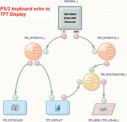
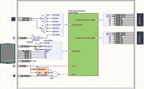
This IP-based system is then connected to the ‘outside world’ via the FPGA. To establish the connection, the peripheral hardware ports are assigned to corresponding physical FPGA pins. The peripherals communicate via the Wishbone bus standard with the processor.
The following peripheral IP cores are used: a PS/2 controller to read the keyboard characters; a TFT display controller for echoing the characters on the display; an SRAM memory controller giving the embedded application access to 1 MB of external SRAM in addition to the internal FPGA embedded RAM.
Since both the TFT display controller and the TSK3000 processor need to address this external RAM, an arbiter is used to allow multiple masters to access the SRAM. The arbiter is priority controlled in this application, with the TFT display being allocated a higher priority than the TSK3000 processor. Alternatively, the arbiter can apply round-robin scheduling, allocating a short period of memory access to each master in turns.
The Wishbone interconnect ports determine where the periphery is mapped in the peripheral I/O range of the TSK3000 processor. If required, the mapped area can also be reconfigured via these interconnect ports. Periphery control is one of the most important tasks of a processor in an embedded application. This requires appropriate driver functions. Since writing and testing these functions oneself is a time-consuming task, it is more convenient to use third-party peripheral driver libraries which already contain the functions for operating the periphery.
The Software Platform Builder
The software contains various peripheral IP cores that can be used in an embedded application. User-friendly configuration and operation of these peripherals is guaranteed via a software framework called Software Platform Builder.
The great benefit for users is that they no longer have to write functions for these low-level peripheral drivers themselves, but can access ready-made library functions in the C source code. Users thereby save the time and effort necessary to familiarise themselves with the internal functioning of the periphery, SFRs, communication protocols and interrupt usages.
The periphery itself is configured by entering the appropriate parameters in the Software Platform Builder document or by activating the available C library functions.
Since the peripheral controller is addressed via memory mapped I/O, it is possible to automatically import the configuration from the FPGA project in order to update the Software Platform Builder configuration at the touch of a button. This is necessary, for example, if the memory mapping has changed or the number of control lines needs adjusting, for instance when four I/O ports instead of one shall be addressed and two additional address lines are required.
The Software Platform Builder is divided into three levels: the lowest level, the so-called hardware wrapper level, provides access to basic functions such as the memory mapped peripheral base address or the interrupt assignment. As a rule, this level is only addressed by the master drivers and not directly from the application. However, for simple access to one I/O port, this functionality can also be used. In this case, the hardware wrapper provides automatically generated C macros:
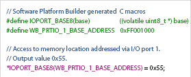
The next level is the driver level. A driver uses the hardware wrapper or another driver to access the periphery. The difference between the hardware wrapper and the driver is that the hardware wrapper provides only basic information to the periphery, but no additional functionality. This information can then be used by the master driver. Each driver has its associated hardware wrapper. If an application accesses a driver directly via the API, it remains hardware dependent because a peripheral change also requires a change of driver.
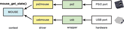
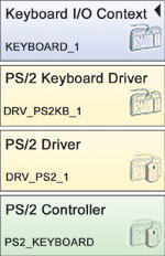
The top level is the context level. This level provides standardised, hardware independent access to the periphery. When context level functions are used, the application remains portable. For example, when using a generic mouse driver, the application code does not change when, for instance, a PS/2 mouse is replaced by a USB mouse. In this case, the software platform will simply swap the slave drivers (Figure 3).
Altium Designer includes support for the following driver services:
* Drivers for SD cards, IDE, Compact Flash and Flash memory.
* Drivers for Ethernet use.
* Kernel services for POSIX compliant multithreading.
* GUI services for creating graphical interfaces.
* Multimedia services for audio and video capabilities.
In addition to the three levels described, software services provide functions, C pre-processor macros and C structures which are not directly related to the periphery. POSIX device I/O services are available to provide access to non-standard I/O peripherals via standard POSIX I/O commands.
PS/2 keyboard driver functions
What may sound quite trivial in the above I/O port control example, changes drastically when tasked with reading characters from a PS/2 keyboard. Again, the first step is to define the base address of the periphery and the addresses for accessing the clock and data lines at the hardware wrapper level. The keyboard interrupt, which indicates when a new character is entered, is serviced on the first driver level, and the new character is then read via the data line. C library functions of the Software Platform Builder which are available at this level include: ps2_putchar; ps2_getchar to send single bytes to the PS/2 buffer or output them; or even ps2_available_bytes and ps2_check_buffer_full in order to ascertain the number of available bytes in the buffer or to determine whether the PS/2 buffer is full.
The keyboard sends the data via a scan code which consists of 11-bit data frames, each transmitting one byte. These data are analysed on the second driver level. If, for example, 0xC1 is received, it means that the letter ‘A’ was typed. Second driver level functions include ps2kb_get_scancode or ps2kb_setleds to read the complete scan code instead of individual bytes or to modify the status of the keyboard LEDs.
At the context level the data are then interpreted and buffered, and the received letter ‘A’ is displayed directly. This is where the standard POSIX I/O commands can be used (Figure 4).
The embedded project
The embedded project consists of a C module and a Software Platform Builder document. The C/C++ compiler for the TSK3000 is included in Altium Designer. After linking the embedded project and the FPGA project to each other, it is possible to import the used peripheral components in the Software Platform Builder via the ‘Import from FPGA’ function. Once this has happened, the FPGA project will recognise and display the components of the lowest level, ie, the hardware wrapper for the PS/2 controller and the VGA TFT display.
Additional drivers and context levels can now be added via a ‘Grow Stack Up’ function. For the PS/2 controller ‘Keyboard I/O Context’, and ‘Text Display Context’ for the VGA TFT display controller signify top level context. In order to be able to use the standard I/O directly, the standard I/O options have to be activated and the keyboard and TFT display assigned stdin and stdout device names respectively (Figure 5).
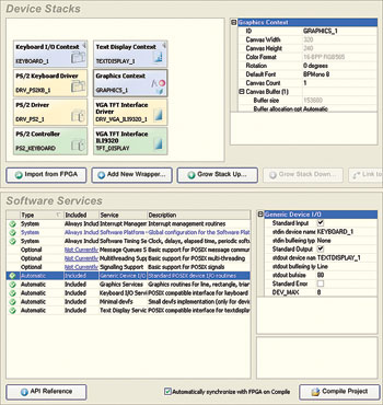
To automatically initialise the peripherals, the options ‘Generate Initialisation Code’ and ‘Call Initialisation Code’ are selected. Next, the respective function calls for initialisation are generated and these functions will then be called by the Startup Code of the embedded project. At the beginning of the main loop it is then possible to access the hardware immediately. The remaining C code for this application example is then reduced to a few lines thanks to Software Platform Builder support:
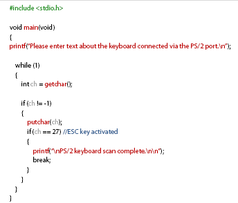
Once this brief instruction set has appeared on the TFT display, test inputs can be made via the PS/2 keyboard. Activating the ESC key will end the program.
Alternative I/O peripheral devices
If multiple I/O peripheral components are used simultaneously, the additional components are addressed via the standard C library functions fopen(), fprintf(), fgetc(), fputc(), fclose().
As an alternative to echoing characters on a TFT display, it is possible to output them via a serial interface or a virtual terminal interface. Similarly, characters can be entered via a USB keyboard instead of a P/S2 keyboard or the serial interface can also be used. This requires very little adjustment: only the peripheral component needs to be changed in the OpenBus system document and the schematic for the modified FPGA pin assignment. After that, the Software Platform Builder document has to be updated to configure the revised stdout/stdin device.
Conclusion
The Software Platform Builder includes modules at different abstraction levels (stacks). Context modules can be superimposed upon driver modules in order to achieve hardware independence for optimal application portability. However, using the APIs of the modules from the lower stack levels can also be appropriate.
While context modules offer the advantage of hardware independence and are very easy to use, the trade off for this ease and comfort is all too often a performance loss in the application. Nevertheless, such an approach provides a very quick way to develop and test different methods and algorithms for an application without having to write time-consuming low-level routines. Designers can therefore focus very quickly on the essential - namely, the application itself.
| Tel: | +27 12 665 0375 |
| Email: | [email protected] |
| www: | www.edatech.co.za |
| Articles: | More information and articles about EDA Technologies |


© Technews Publishing (Pty) Ltd | All Rights Reserved
 printer friendly version