


As well as electrical properties, price is a key criterion for selecting power line filters. But decisions made on this basis must often be revised because important background conditions have not been taken into account. Designers of shielded enclosures must take a closer look at intended applications before they can choose the right power line filter.
Shielded enclosures provide protection against electromagnetic fields. Depending on application, either the enclosure is shielded from its electromagnetic environment, or the surroundings are protected against electromagnetic emissions from the enclosure.
In the first case, R&D labs, test centres, computer systems or medical apparatus can only function properly if they are adequately protected against radio-frequency energy. In the second, eg high-voltage tests and measurement of disruptive field strengths, the RF energy generated would interfere not only with radio and television reception, but also with operation of nearby electrical equipment. To prevent interference or voltage surges from passing in or out of shielded enclosures along the leads, all cables running through the shielding must be equipped with suitable filters.
Common and differential-mode interference
Before filter circuits can be designed, propagation of conducted interference must be examined. Interference from an ungrounded source is initially propagated only along the leads connected. Like the line current, the interference current flows along one conductor to the equipment disturbed and back to the source along the other. The two currents are out of synchronism. This is known as differential-mode or symmetrical interference.
However, parasitic capacitances in the interference source and the equipment disturbed, or intentional ground connections, also generate an interference current in the ground circuit. This current flows along the two terminal leads to the equipment disturbed and back to the source along the ground conductors. The two currents on the terminal leads are in synchronism. This is known as common-mode or asymmetrical interference.
Both interference currents flow through interference suppression chokes located in the current path. The function of these chokes is to attenuate the interference currents while allowing the operating current to pass through with minimum voltage drop.
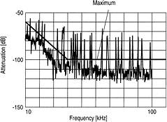
It is defined as the attenuation produced when the device under test is inserted into a test configuration with an impedance Z. The attenuation curves plotted over the frequency allow different filters to be compared. Test set-ups are commonly based on CISPR 17 with an impedance Z of 50 Ohm; they are used for differential-mode, common-mode and single-mode measurements.
Electrical properties of power filters
As well as having good RF properties, filters for power lines must be able to withstand high voltages and currents. But they can only be miniaturised to a limited extent because they must maintain tolerances such as air gaps and creepage paths and because their interference suppression chokes and capacitors must be designed for high operating currents and voltages.
The technical limits of power filters depend on rated voltage and current, line frequency, duration of operation, ambient temperature, permissible reactive current and voltage drop as well as the attenuation required and frequency range to be blocked. As a rule, the results obtained from filters with more than three stages are disproportionate to the expense.
Basically, power line filters are designed as low-pass filters with capacitors in the voltage path and inductors in the current path. The capacitors discharge the interference signals to the filter casing, whereas the chokes attenuate the interference currents, but let the operating current pass with minimum voltage drop.
Single chokes attenuate common and differential-mode currents equally well. The large shearing effect caused by the external air gap in I-core chokes, for example, prevents saturation of the magnetic core by the operating current. The disadvantage of single chokes, however, is that they tend to become bulky and expensive for high operating currents.
Current-compensated chokes basically attenuate only common-mode interference currents, as the magnetic fluxes induced by the operating current and differential-mode interference current in the core are cancelled out by coils wound in opposite directions. These chokes have the advantage of a relatively small volume even for high operating currents. Insufficient attenuation of the differential-mode interference currents can be compensated by high capacitances between the lines (Figure 1).
Filter circuit design
Basically, two circuit designs can be used for power line filters, each with its on pros and cons. A primary distinction is made between filters in circuits with low leakage currents (Figure 1) and filters with single chokes (Figure 2).
The capacitors in these filters are connected between the phase conductors and the neutral conductor to discharge the interference signals. As a result, the 50 Hz reactive currents generated in these capacitors flow to the neutral conductor and do not apply any load to the ground conductor. Capacitors connected between the neutral conductor and casing then discharge the interference signals. As only the relatively low differential voltage between neutral and grounded conductors is present at these capacitors, the 50 Hz leakage currents remain low in these filters.
However, the disadvantage of low leakage current design is that owing to the series circuit through the neutral conductor, the capacitors are less effective than in filters with single conductors. This must be compensated by high-inductance chokes in the current path. For this reason, current-compensated ring core chokes are always used in these filters. But care must be taken with ring core chokes that current compensation is sustained so that filter attenuation is not reduced. Current compensation means that the forward and return currents are equal. Leakage currents from downstream loads are not permitted (Figure 3).
The effect of the differential current on current compensation and the associated loss of inductance is shown in (Figure 3). Even at a differential current as small as 2% of the rated current (eg 320 mA for a choke with a rated current of 16 A), the choke loses 60% of its inductance.
This means that the user must check the loads for the presence for leakage currents. Operation of a line impedance stabilisation network may present problems because its leakage current drives the choke into saturation, significantly reducing filter attenuation. These filters are just as problematic if the voltage difference between the neutral and ground conductors is too high, as may be caused if terminal leads are long and current consumption high at the same time (Figure 4).
As this saturation takes place at every half-wave, interference voltages may even occur on the power line. The interference voltages shown in (Figure 4) are created in the filter by saturation at a voltage difference of more than 6 V between the neutral and ground conductors, thus reducing the dynamic range of the measurement by more than 40 dB.
In these single-conductor filters, the lines to be filtered are designed as individual conductors, ie each lead is connected to the filter casing with capacitors and single chokes in the current path. This circuit is more elaborate, requiring four single chokes instead of one compact ring core choke in a four-line filter, for example. However, it is more versatile because there is no need to worry about reactive currents from loads. Voltage differences at the filter input are just as uncritical. Nevertheless, the chokes in the current path must be carefully designed, ie the inductance must remain stable right up to the rated current. The 50 Hz reactive currents generated in the capacitors must be discharged as leakage currents via the ground conductor.
Typical applications
As both designs described here have their pros and cons, the choice of power line filter will be determined by the application, as the following examples show.
Supplying power to devices under test in EMC test chambers calls for versatility because different loads with different properties are connected. Only filters with single conductors should therefore be used. This makes sure that filter characteristics remain constant and unaffected by loads.
For other loads in test chambers, such as lighting and ventilation, compact filters of low leakage current design can be used.
Filters of low leakage current design can likewise be used in chambers testing the reliability of ungrounded industrial power supply systems, because the loads involved are defined, transparent and do not change significantly. In addition, the leakage currents on the ground conductor are kept low.
To shield larger buildings such as anechoic chambers or military installations, single-conductor filters should also be used, because leakage currents emanating from the EMC filters in these installations can generate saturation in filters of low leakage current design.
Summary
In shielded enclosures, the right choice of power line filter largely depends on whether leakage currents are generated by downstream electrical loads. If leakage currents are high (greater than 1% of rated current) or cannot be defined, single-conductor filters provide greater protection. Filters with low leakage currents can be used if the installation is transparent and leakage currents can be calculated.
| Tel: | +27 11 458 9000 |
| Email: | [email protected] |
| www: | www.electrocomp.co.za |
| Articles: | More information and articles about Electrocomp |


© Technews Publishing (Pty) Ltd | All Rights Reserved
 printer friendly version