


5G is not simply an iteration of 4G.
It is truly revolutionary and will change everything we know today. For the past 30 years, we have traversed through:
• 1G (the 1980s, AMPS/ETACS) mobile network, which brought analog voice to the masses.
• 2G (the 1990s, GSM/CDMA), which made digital voice available and increased network capacity dramatically with the advancement of the integrated circuit and digital signal processing.
• 3G (the 2000s, WCDMA/EVDO), which combined mobile data with voice, enabling customers to make a voice call while replying to email for the first time.
• 4G (the 2010s, LTE), which was all about wireless Internet (mobile IP) at higher speed and desktop applications finally arrived on smartphones.
Nevertheless, there is still segmentation between the communications industry and customers. There are wireline/Internet providers, cable TV and Internet service providers, wireless operators, over-the-top (OTT) application providers and more.
Consumers and businesses get connections from various operators on different platforms that often do not communicate with each other. There are significant overhead expenses in the networks and providers allocate substantial resources to manage these expenses (signalling, billing and device management).
5G is a connected application ecosystem for end users. Each application will adaptively manage data speed, latency and reliability, depending on the tasks. For example, a vehicle on autopilot requires a reliable instant response and a secure link at highway speeds. A 5G network will provide wide coverage, low latency and an encrypted communication link. Blindly assigning a 100 MHz channel for the car will not work because higher throughput does not equal short latency and reliable coverage.
From the perspective of network operators, 5G will consolidate all their communication systems under one package to meet end-user application needs; such as data, voice, video, Internet of things and critical communications. 5G will provide much higher throughput, ultra-low latency, increased network capacity, reliability and secure services.
The 5G network architecture should provide:
• Massive capacity; 1000 times more than 4G.
• Super-fast data rate; 100 times more than 4G.
• Ultra-low latency; less than 1 ms.
To achieve these goals, network and user equipment manufacturers must invent innovative technologies to make the network drastically more efficient. They must also deploy a new spectrum to support much wider bandwidth requirements.
There are three key technologies that 5G requires: millimetre-wave (mmWave) network deployment, massive multiple-input multiple-output (MIMO) and beamforming.
5G presents uncharted territory for RF engineers. How to characterise a mmWave air interface? How to measure antenna efficiency? What are the potential interference issues in 5G networks? What solutions can address 5G over-the-air (OTA) measurements to help evaluate 5G trial networks?
mmWave band for 5G deployment
LTE with 20 MHz bandwidth and 64 QAM can achieve 100 Mbps data rate on the downlink. However, for 5G to provide 100 times higher data rates, it will require much wider bandwidth standards. The current sub-3 GHz cellular band cannot support wider bandwidths. The only way to implement 5G is to move the system to a higher frequency band.
5G requires a much higher bandwidth; as much as 800 MHz to 2 GHz. The frequency bands that have such potential are mmWave bands. The deployment of satellite communication in the Ka band (26,5 GHz to 40 GHz) increased channel bandwidth – from a typical bandwidth of 54 MHz to 500 MHz through 2 GHz and was accompanied with spot beam frequency reuse to achieve gigabit IP connection.
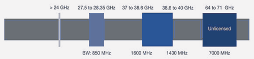
In October 2015, the FCC allocated three mmWave bands for 5G services; these bands are the frontier spectrum for 5G services. Spectrum above 24 GHz is currently under investigation.
The 28 GHz band supports 850 MHz of bandwidth and the 37-40 GHz band supports 3 GHz of bandwidth. An unlicenced band from 64,71 GHz supports 7 GHz of bandwidth. These spectrum and bandwidth allocations make the 5G service possible.
mmWave link propagation and link budget
Commercial wireless service frequencies are below 6 GHz, including Wi-Fi. The channel characteristics of these bands are well understood with many design tools available to use. However, deploying mmWave frequency bands to provide a link between user equipment (UE) and base station presents many technical challenges. It is essential to understand mmWave path loss properties and build a predictable mathematical model.
Path loss and link budget are two essential elements while investigating 5G link behaviour.
5G link includes line-of-sight (LOS) and non-line-of-sight (NLOS) components in the radio propagation environment. LOS is close – but not exact at above 60 GHz – to free space path loss, whereas NLOS path loss deviates significantly from free space.
The typical process is to make a propagation loss measurement at a specific frequency and terrain. You can then perform a curve fitting to find the loss of exponent n. The combined path loss is proportional to the distance between transmit and receive antenna n – where n is the loss of the exponent, which can range from 2 to 4.
Free space path loss = (4πd/λ)2 (d: distance; λ: wavelength)
Free space path loss in dB = 92,45 + 20 log(distance in km)
+ 20 log(frequency in GHz)
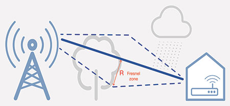
Point-to-point microwave communications require a clearance between the propagation path and the nearest obstacles on the ground, which is governed by Fresnel zone theory. If the zone is 60% clear, it is LOS propagation. 5G networks, however, will have much lower antenna height, which could potentially introduce significant propagation blockage.
5G mmWave link budget is quite different from the traditional
sub-6 GHz wireless link budget and can cause further losses due to rain fade, shadowing loss, foliage, atmosphere absorption, humidity and Fresnel blockage.
The following is an example calculation of 5G link budget that could vary depending on the band and type of cell:
• Received power in dBm = Tx power + Tx antenna gain + Rx antenna gain - path loss
• Rain fade (2 dB/200 m) - shadowing loss (20 to 30 dB) - foliage loss (10 to 50 dB)
• Atmosphere absorption - terrain /humidity - Fresnel blockage - system margin
• Fresnel zone radius (R) = 17,32 x √(d/4f) (d in km, f in GHz)
By examining the above equations, it is obvious that many factors can impact mmWave links. The link budget is the most critical area of focus for any 5G deployment team.
Propagation loss measurements with FieldFox
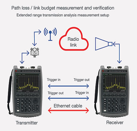
Keysight’s FieldFox handheld microwave analyser has an operating mode known as extended range transmission analysis (ERTA). ERTA requires a connection between two FieldFox instruments, with one acting as the transmitter and the other as the receiver.
Triggers on each box synchronise the measurement. An Ethernet connection sets the frequency range and transfers the results from the transmitter to the receiver. The receiver is always the master in this setup. The splitter at the transmitter side measures the output power from the transmitter, so the receiver side knows the exact transmitting power level. FieldFox can record real-time data, replay the data and then export it for post-analysis.
When longer distances are necessary for the measurement and physical cable connections are no longer viable, then an external laptop controls both FieldFox instruments. You can implement a software trigger to reduce the speed to perform the ERTA measurement.
Massive MIMO
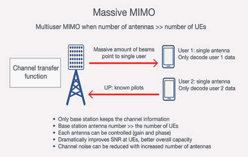
Massive MIMO is an extension of multiuser MIMO; the number of base station antennas is much higher than the number of UEs in the cell. The average number of antennas is 48 to 64. The increase in the number of antennas makes the beam much narrower to allow the base station to deliver RF energy to the UE more precisely and efficiently.
You can control the antenna’s phase and gain individually; the channel information remains with the base station. This type of implementation simplifies UE design without adding multiple receiver antennas. Installation of a large number of base station antennas will increase the signal-to-noise ratio (SNR) in the cell, which leads to higher cell site capacity and throughput. As 5G massive MIMO implementation is on mmWave, the physical size of the antenna is small and is easy to install and maintain.
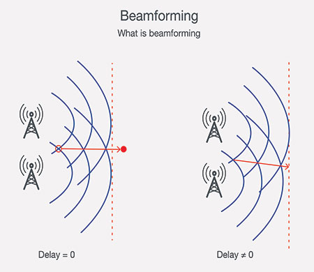
Beamforming
You can control the element of a phased array antenna through beamforming.
Beamforming achieves better efficiency to overcome path loss, channel noise and channel crosstalk. At mmWave, the path loss is much more significant than sub-6 GHz channel; beamforming is crucial to the success of a 5G network.
Figure 5 shows how beamforming works. On the left side, the delay between two-phased elements is 0. The wave travels straight. When adding delay, the wave changes direction. The base station can steer multiple beams to multiple UEs simultaneously when controlling the individual array antenna.
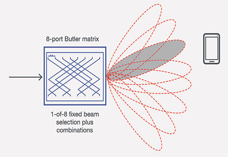
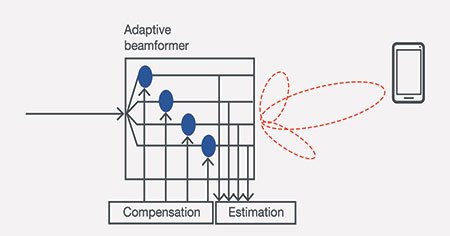
5G beamforming has three stages: beam acquisition, feedback and change. In the beam acquisition phase, the base station does a beam sweep, sends out a beam to eight different directions in one symbol, the UE detects the best beam and transmits the random access channel (RACH) to the base station. In feedback and change stages, the UE sends the ranking list of beams to the base station, the best possible beam steers toward the UE. Lastly, during data transfer, the UE can continuously provide feedback to the base station to make small adjustments of the beam to achieve a better SNR.
5G mmWave coverage verification
mmWave band adoption is critical for 5G implementation. mmWave frequencies allow the network to provide much faster data rates and precise sensing networks for IoT.
A typical network deployment begins with network planning. Engineers use RF network planning software to design 5G networks based on both site survey data and link budget assumptions. In most cases, the design does not match the real performance of the network. Verification and optimisation are necessary after installation. Not matching the real performance of the network is particularly true for mmWave 5G networks.
The first step is to verify that the network does not have any
coverage gaps. You can perform this check by measuring the
coverage against the network design. For sub-3 GHz networks like LTE, engineers use scanning receivers with omnidirectional antennas that match UE antenna characteristics to measure signal strength and control channel power from the base stations. Because the omnidirectional antenna receives energy from all directions, this is the best method to perform network coverage testing.
However, using omnidirectional antennas as receiving antennas is no longer feasible in a 5G mmWave network because:
• The 5G UE antenna is a phased array antenna.
• The 5G mmWave gNB antenna is a phased array antenna with beamforming.
• The UE can only use a particular set of multipath signals; the omnidirectional antenna is no longer representing UE RF reception performance.
An innovative approach is necessary to make an actual 5G mmWave network coverage test. Instead of using an omnidirectional antenna, a phased array antenna with a spectrum analyser or scanning receiver is necessary to measure network coverage.
The phased array antenna-based coverage measurement system can steer measuring beams to evaluate:
• Beam power from the gNB to calculate network coverage.
• Multipath impact evaluation.
• Simulate UE antenna performance to estimate potential UE coverage issues.
By changing the beam width, the phased array antenna is configurable as an RF probe to measure gNB parametric performance over the air.
In a typical LTE coverage test, the omnidirectional antenna-based measurement receiver takes one data point per geolocation. You can generate many samples at the location to achieve a better statistical value of the power level.
In contrast, the 5G mmWave requires geolocation, azimuth and elevation to represent each data point. This requirement creates tremendous challenges for RF engineers to perform the network test. There are only a few systems available that can make such measurements.
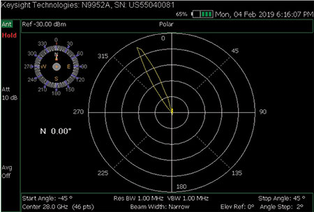
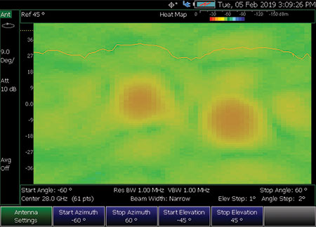
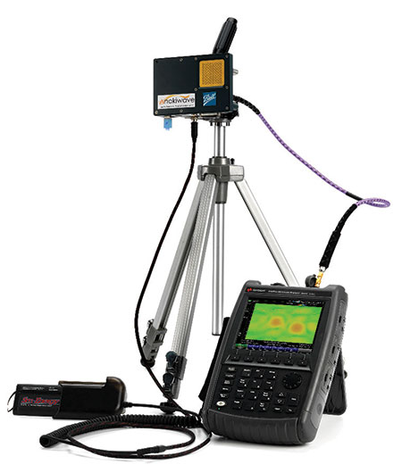
Keysight’s FieldFox analyser is equipped with a spectrum analyser and integrates an 8x8 phased array antenna to enable 5G coverage test. The instrument controls the measuring beam to sweep from 0 to
120 degrees in azimuth and 0 to 90 degrees in elevation. The generated heat map shows the coverage in any location. You can log the data with geotags and export to any network planning tools to facilitate beam optimisation.
Phased array antenna pattern and phase delay test
Because a 5G base station radio and its phased array antenna integrate into a single hardware unit, there is no RF connector at the antenna to allow test equipment to measure return loss and voltage standing wave ratio (VSWR). However, it is necessary to know the performance of the antenna.
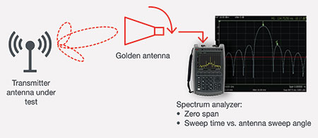
Antenna beam width from a mmWave phased array antenna is very narrow, which means its energy can be steered toward an over-the-air coupling probe; in this example, a horn antenna. The spectrum analyser measures the antenna pattern of the array and the isolation between the main lobe and side lobe.
Figure 11 shows how the spectrum analyser is configurable to verify the antenna pattern. The spectrum analyser configures as a zero span. Set sweep time long enough to synchronise to the rotation of the golden antenna.
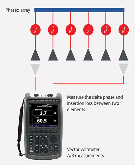
A 5G phased array antenna has many elements; 64/128/256. Each element’s phase is adjustable and it is important to know whether the adjustment can translate into phase shift over the air.
A network analyser with a vector voltmeter (VVM) measures the phase shift between two receiving ports. Choose one of the elements as a reference and connect it to port 1 – that connection can be via an antenna probe. Port 2 is attached to the element under test. The VVM reports the delta phase and magnitude between the two elements. The delta phase is the phase adjustment of the phased array antenna.
FieldFox microwave analyser helps to fast-track 5G deployment
The FieldFox microwave analyser integrates many key mmWave tests into one package to enable 5G pre-deployment tests and ongoing maintenance. Since 5G is still in the development stage, the technology will change along with standardisation development, therefore additional new tests are necessary. FieldFox is a software-defined instrument; all measurement capabilities are via software licences, except for frequency.
FieldFox can perform many 5G necessary tests during the deployment stage:
• Frequency coverage: 9 kHz to 32/44/50 GHz.
• Spectrum analysis.
• Phased array antenna beam scanning.
• Interference analyser with record and playback.
• Built-in mmWave continuous wave independent source.
• Real-time spectrum analyser with record and playback.
• Channel scanner with Google map file format (CSV/KML) support.
• Built-in power meter.
• Extended range transmission analysis.
• Vector voltmeter.
• Cable and antenna analyser.
• Vector network analyser.
Also, FieldFox has a rugged design and is battery-powered. It has no fans or vents, can operate from -10°C to +55°C and meets the IP53 standard.
Summary
Deploying 5G on mmWave presents many challenges to RF engineers. It is essential to have a robust channel model for 5G mmWave frequencies. Massive MIMO and beamforming are an integral part of 5G and early extensive tests are necessary to enable deployment.
Keysight’s FieldFox analyser provides propagation loss test, antenna pattern over-the-air test, phased array antenna-based measurement system and many other standard mmWave tests in a single instrument. It greatly improves the efficiency in 5G pre-deployment, first-office applications and ongoing maintenance.
| Tel: | +27 12 678 9200 |
| Email: | [email protected] |
| www: | www.concilium.co.za |
| Articles: | More information and articles about Concilium Technologies |


© Technews Publishing (Pty) Ltd | All Rights Reserved
 printer friendly version