


This article continues from the 9 November issue of Dataweek.
Earth fault current measurement
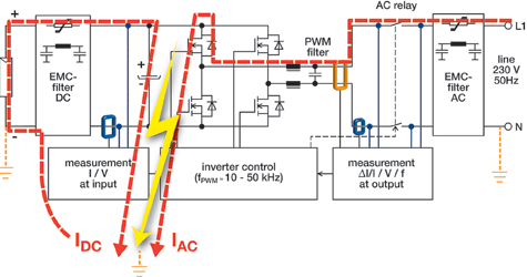
For safety reasons, the earth fault current, arising from an insulation defect (Figure 5), has to be monitored in transformerless designs. The transducer used to measure the earth fault current must be able to measure AC and DC signals as the earth fault current could be AC or DC, depending on where the fault (for example, a short circuit) occurs, and depending on whether the PV panel is grounded or not. Similar requirements to those for the leakage current measurement apply. Accuracy, while still important, is less of a consideration in this case, as short-circuit currents are higher than the leakage currents.
All of these residual current measurement needs in PV transformerless inverter designs are a fundamental safety requirement; they must conform to all relevant standards and there can be no compromise on security or reliability of the leakage current measurement function.
Closed-loop fluxgate technology
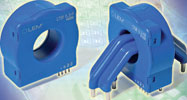
To achieve the targets in terms of accuracy with small currents, LEM applied its closed loop fluxgate technology and created the CTSR current transducer range (Photo 2). Closed loop current transducers measure current over wide frequency ranges, including DC. They provide contact-free coupling to the current that needs to be measured, in addition to safe galvanic isolation and high reliability. Their output signal is an accurate, high-resolution image of the primary current with a very short delay.
In higher frequency ranges, these transducers function exactly the same way as (passive) current transformers, where a relatively small induced voltage in the secondary winding drives the secondary current in the secondary winding and, most important, through the load resistor. A low induced voltage equals low magnetic flux in the magnetic core, which results in good accuracy. Low flux means a small difference between primary and secondary current linkage (current linkage is the product of current multiplied by the turns count of the winding).
For DC, and in low-frequency ranges, the induced voltage is too low to drive the secondary current, so the intrinsic error of simple current transformers increases with decreasing frequency. In this domain, the magnetic flux density in the transducer’s core is measured by a sensing element and a voltage is applied to the secondary circuit that, overall, maintains the flux density near zero, effectively creating a closed control loop.
CTSR features
The CTSR transducer series exhibits certain differences from LEM’s standard closed loop transducers. The Hall element used for feedback is replaced by a fluxgate detector, selected because of the need for better feedback; better in this case basically means a higher voltage developed per unit of current linkage, a measure that is called open loop sensitivity. The fluxgate’s low offset drift also explains its selection.
The magnetic head of the CTSR has been optimised to measure the residual current (the algebraic sum of the currents flowing in the wires that pass through the aperture of the transducer). This residual current should be a maximum of only a few hundred mA (compared to the main current of, typically, several tens of Amps in each wire).
The CTSR embodies a number of additional functions that enhance its applicability to the PV inverter residual current measurement problem; it contains a self-test function activated via the reference pin, that verifies correct operation; it has a demagnetisation function, also accessed through the reference pin or at power-on, that removes any magnetisation offset; and, it is suitable for use on both single-phase and multiphase grids.
The complexity of a fluxgate-based current transducer is comparable to that of a transducer based on a Hall effect IC. In both, some AC signal processing and synchronous rectification is applied. The fluxgate transducer additionally requires a fluxgate detector. Despite the complexity of the signal chain, use of a custom IC keeps the device at a competitive cost level when compared to Hall effect current transducers.
Within this custom IC, circuit elements form an oscillator coupled to the fluxgate, that drives it into saturation each half cycle, at a frequency of several hundred kHz. In this configuration, a change in the duty cycle of the driving voltage will occur when a DC magnetic flux is present in the fluxgate core; this property provides the mechanism to detect a residual flux in the main transducer core.
Signal processing
The signal processing stages in the IC (Figure 6) comprise duty cycle demodulation, frequency response compensation, an integrator and a bridge amplifier that provides the secondary current. This output architecture can provide a higher (doubled) voltage to the secondary circuit when compared to a single output stage, with the other side of the circuit connected to a reference potential at typically 2,5 V. In this configuration, the load (or measurement) resistor is floating, so in order to obtain an output signal referenced to a fixed voltage, a difference amplifier is used which is also part of the IC.
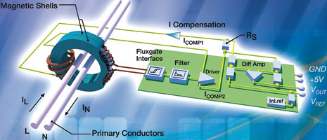
Table 2 sets out the major parameters of the CTSR 0.3-P or –TP and CTSR 0.6-P or –TP devices, that safely measure residual current between IL and IN (for instance in case of a leakage to earth) with nominal values of 300 mA and 600 mA respectively. Referring again to Figure 6, the magnetic core comprises a pair of two magnetic shells containing the fluxgate. This construction has the advantage of protecting the fluxgate against any parasitic magnetic field.
| Model | Rating IPRN(mA) | Measuring range IPRM (mA) | Linearity (% of IPRM) | Supply voltage (V DC) | Reaction time @10% of IPRN tra (µs) | Response time @90% of IPRN tr (ìs ) | Accuracy @ +25°C (without off set) % of IPRN - MAX | Frequency Bandwidth (kHz) (-1 dB) |
| CTSR 03-P | 300 | ±500 | 0,5 | +5 ±5% | 7 | 50 | 1,9 | 3,5 |
| CTSR 0 6-P | 600 | ±850 | 0,4 | +5 ±5% | 5 | 50 | 1,5 | 9,5 |
| Analogue voltage output (V) @ IPRN | Current consumption @ IPRN (mA ) | Offset drift (ppm/K of 2,5 V) | Gain drift (ppm/K) MAX |
| VREF ±1,2 | 17,8 Unipolar | 50 | 400 |
| VREF ±1,48 | 18,1 Unipolar | 60 | 100 |
Using the closed loop fluxgate technology has achieved accurate measurement of these very small residual DC or AC currents with very low offset and gain drifts over the wide operating temperature range from –40°C to +105°C.
The devices are PCB mountable and lightweight (28 g), with a 20,1 mm diameter aperture that easily accommodates multiple conductors. The residual current capability measures the sum of all of the instantaneous currents flowing through the aperture, in single- or three-phase configurations with a high overload potential up to 3300 A for a pulse duration of 100 μs, and with a rise time of 500 A/μs. Conductors may be carrying primary currents of up to 30 A/wire, AC or DC.
Standards compliance
LEM followed the latest safety standards that have been issued in respect of solar installations and inverters, namely VDE 0126-1-1, UL 1741, DK 5940 and IEC 60950-1, in the design of this range of products. Incorporating high creepage and clearance distances (11 mm) and CTI (comparative tracking index) of 600 V, they provide high insulation. Power supply requirements of +5 V d.c. and access to the internal reference make the CTSR models fully compatible with modern power electronics.
An additional pin provides access to the internal reference voltage (2,5 V) which can be used as the reference voltage of an A/D converter; this extra pin can also accept the internal reference (from 2,3 to 4,0 V) of the digital signal processor or A/D converters commonly used in power electronics, allowing cancellation of the reference temperature drift.
CTSR transducers can also be supplied with a primary inserted conductor made up of four individual conductors (CTSR xxx-TP models), where three conductors can be used for a three-phase system and the additional one can be used for test purpose or for the neutral. Models with higher nominal current range up to
3 ARMS can be developed on request to meet specific needs.
| Tel: | +27 11 626 2023 |
| Email: | [email protected] |
| www: | www.denver-tech.co.za |
| Articles: | More information and articles about Denver Technical Products |


© Technews Publishing (Pty) Ltd | All Rights Reserved
 printer friendly version